S200/S201/S210/S211/Z200
Diagrams 10
10-6
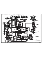
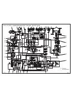
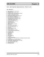
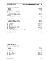
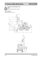
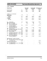
10.2.2 AS 210 hydraulic diagram (bolt lock), “35 km/h” model
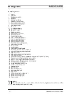
Item Designation
01 Swivel cylinder DW 110/45/910/1287
02 Supporting valve
03 Supporting cylinder EW 70/210/470
04 Reservoir system, pipe break protection (option)
05 Auxiliary hydraulics, external circuit
06 Locking cylinder DW 40/63/70/397
07 Shift valve for locking the quick-change device
08 Lift cylinder DW 110/70/908/1317
09 Pipe break protection, lift cylinder (option)
10 Tip cylinder DW 110/70/545/1015
11 Pipe break protection, tilt cylinder (option)
12 Unpressurised return line (option)
13 Lifting device suspension
14 Steering cylinder 80/40/152/472.5
15 Double shock valve
16 Steering switching valve
17 Blocking valve
18 Steering unit, 300/100 cm³/rev.
19 Priority valve
20 Drive motor A6VM 160 EP2D
21 Gear-type pump (51+27) cm³/rev.
22 Drive pump A4VG 125 DA
23 Drive motor
24 Gear-type pump 14 cm³/rev.
25 Suction strainer
26 Electric contamination indicator
27 Combined suction and return flow filter
28 Hydraulic oil tank
29 Hydraulic oil cooler
30 Hydrostatic fan
31 Shut-off valve
32 Brake valve
33 Lamella brake
34 Parking brake valve
35 1-way valve
36 High-pressure transition
37 Combination valve: pipe break protection / lifting device suspension (option)
38 3-way valve
39 Control pressure valve, auxiliary hydraulics
40 Control pressure transmitter, working hydraulics
41 Shut-off valve, working hydraulics
42 Four-wheel drive shutdown valve
43 Differential lock valve
44 Hydraulic gear shift
Summary of Contents for AS 210
Page 7: ...Safety Regulations ...
Page 19: ...Signs ...
Page 22: ...ProtectionAgainstTheft ...
Page 25: ...Description ...
Page 33: ...Operation ...
Page 44: ...Attachments ...
Page 53: ...Rescue Towing Lashing Lifting by Crane ...
Page 60: ...Maintenance ...
Page 78: ...Faults Causes and Remedies ...
Page 81: ...Diagrams ...
Page 98: ...Technical Data Loader ...
Page 102: ...Technical Data Attachments ...
Page 115: ...AdditionalOptions Modifications Notes on Inspection for Loaders ...


