background image

April 2022

MS-SVN083A-EN

Installer’s Manual

DC Inverter U-match Series for R410A Unitary 

Split Air Conditioner

Models:

HP Outdoor Units: 


4TXD2036A10NUA
4TXD2060A10NUA

HP Indoor Units: 


4MXA2024A10NUA
4MXA2036A10NUA
4MXA2048A10NUA
4MXA2060A10NUA

Summary of Contents for 4MXA2024A10NUA

Page 1: ...3A EN Installer s Manual DC Inverter U match Series for R410A Unitary Split Air Conditioner Models HP Outdoor Units 4TXD2036A10NUA 4TXD2060A10NUA HP Indoor Units 4MXA2024A10NUA 4MXA2036A10NUA 4MXA2048A10NUA 4MXA2060A10NUA ...

Page 2: ...ese requirements could result in death or serious injury WARNING R410 A Refrigerant under Higher Pressure than R 22 The units described in this manual use R410 A refrigerant which operates at 50 to 70 higher pressures than R 22 Use only R 410A approved service equipment Refrigerant cylinders are painted with pink color to indicate the type of refrigerant and may contain a dip tube to allow for cha...

Page 3: ...ronment our customers and the air conditioning industry All technicians who handle refrigerantsmustbecertified TheFederalCleanAirAct Section608 setsforththerequirements for handling reclaiming recovering and recycling of certain refrigerants and the equipment that is used in these service procedures In addition some states or municipalities may have additional requirements that must also be adhere...

Page 4: ... Pipes 12 Refrigerant Piping at the Outdoor Unit 13 Insulating the Refrigerant Piping and Connections 13 Piping Requirements 14 Screw Connection 15 Vacuum and Refrigerant Leakage Detection 15 Electrical Installation 17 Requirement and Notice on Electrical Installation 17 Electrical Parameters 17 Connection of Power Cords andThermostat Wires 17 Check after Installation 21 Test Running 22 Maintenanc...

Page 5: ...shock or fire 8 Use the specified types of wires for electrical connections between the indoor and outdoor units Firmly clamp the interconnecting wires so their terminals receive no external stresses Incomplete connections or clamping may cause terminal overheating or fire 9 After joining the interconnecting and supply wiring shape the cables so that they do not put undue force on the electrical c...

Page 6: ...plate to ensure the proper electrical requirements will be met 5 Check the installation locations to ensure the weight of the units can be supported 6 Check the refrigerant pipe sizes and ensure they have been or will be installed according to the requirements in this manual 7 Check the outdoor unit nameplate for electrical power supply and wiring requirements to ensure the proper wiring has been ...

Page 7: ...essories Cooling Heating OutdoorTemperature 5 F 15 C 129 2 F 54 C 22 F 30 C 75 2 F 24 C Outdoor Unit Accessories No Name Appearance Qty Usage 1 Drain Plug 3 To plug the unused drain hole 2 Drainage Connecter or 1 To connect with the hard PVC drain pipe ...

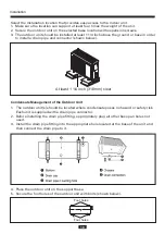
Page 8: ...ers 2 Install at a place with good ventilation Make sure the outdoor unit stays at a well ventilated place with no obstacles nearby that may obstruct the air inlet and outlet 3 Avoid installing at a place with leakage of inflammable gas oil smoke or corrosive gas 4 Keep it away from strong wind because strong wind will affect the outdoor fan and lead to insufficient air flow volume and thus affect...

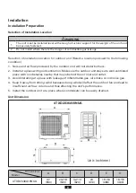
Page 9: ...o the base Refer to local codes for additional requirements When the outdoor unit is surrounded by walls or other obstructions the installation space of the unit should be no less than the clearances indicated below For efficient operation leave three of four directions of peripheral constructions open when possible Unit Installation NOTICE The outdoor unit does not have aTXV thermal expansion val...

Page 10: ...n pipe and connector shown below 1 The outdoor unit s should be located where condensate poses no hazard or safety risk Each unit is supplied with a drain pipe connector 2 Before installing the drain pipe fitting appropriately plug all other base pan holes not used 3 Install the drain pipe fitting into the appropriate hole located at the base of the unit and then connect the drain pipe to it Conde...

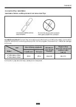
Page 11: ...connection pipe be careful not to damage the pipe Do not over tighten the screw nut otherwise leakage will occur Connection pipe should have water proof insulation Size of fitting pipe inch Maximum pipe length feet m Biggest drop between indoor and outdoor units feet m Liquid pipe Gas pipe 4TXD2036A10NUA 4TXD2060A10NUA Ø3 8 Ø3 4 98 4 30 49 2 15 Item Model Installation ...

Page 12: ...he copper tubing is rolled while being pressed thereby reducing the probability of copper flare cracking 5 Check if the flare part is spread evenly and there are no cracks 1 Use a refrigerant pipe bending tool to shape refrigerant piping smaller diameter piping may allow for light hand bending providing minimum diameter of 6 inches 2 Do not bend the pipes in an angle more than 90 3 When pipes are ...

Page 13: ...ent condensation water leakage and damage to the insulating material 2 The connections at the indoor unit should be wrapped with insulating material No gap is allowed on the joint of the indoor unit as shown below NOTICE 1 To prevent distortion and breaking of the pipe bend the pipe with a radius of curvature of 6 in 150 mm or more Use a tubing bender when forming the copper tubing into a bend 2 I...

Page 14: ...addles NOTE Oil traps are sometimes needed when the outdoor unit is installed higher than the indoor unit An oil trap is needed for each 20 ft 6m of vertical rise on the gas pipe Piping Requirements If the outdoor unit is installed lower than the indoor unit 1 A drain pipe should be above ground and the end of the pipe should not dip into water 2 Tapingpipesmustbedonefrombottomtotop Donotwraptooti...

Page 15: ...and then tighten it with the spanner or adjustable wrench 3 Refer to the torque reference table within this document before tightening to determine the appropriate torque over tightening will damage the nut and lead to leakage 4 Use dry Nitrogen to pressurize the piping circuit with 150 PSIG and allow it to hold while performing other installation processes It is recommended to apply a soap bubble...

Page 16: ...on is complete additional charge is to be added a If no additional charge is required break the vacuum with refrigerant then remove the gauge connectors b slightly open the liquid valve at the outdoor unit allow system to equalize then fully open the liquid valve and then open the vapor service valve 7 After leak checking is complete apply thermal insulation around the flare connections and all ex...

Page 17: ...Parameters Model Power supply Fuse capacity A Maximum over current protection A Minimum circuit ampacity A 4TXD2036A10NUA 208 230V 1Ph 60Hz 35 35 24 4TXD2060A10NUA 208 230V 1Ph 60Hz 45 45 35 Connection of Power Wiring and Thermostat Wires 1 For solid wires as shown below a Use wire cutters to cut off the wire end and then peel away about 1 in 25 mm of the insulation layer b Use a screwdriver to un...

Page 18: ...wered on 2 Match the terminal numbers and wire colors with the colors indicated in the indoor unit Wrong wire connection may burn the electrical components 3 Connect the wires firmly to the wiring box Incomplete installation may lead to fire hazard 4 Connect wiring by referring to the circuit diagram labeled on the unit and securely tighten 5 Ground wire should be connected Installation ...

Page 19: ... outdoor defrosts D of outdoor unit will send 24V signal WARNING 1 High and low voltage wires should be routed through different openings of the electric box cover 2 Use screws to tighten up the thermostat wires and power wiring of unit on the terminal board Wrong connection may lead to fire hazard 3 Ground the unit through connecting the ground wire 4 The units should comply with applicable local...

Page 20: ...he power wiring and thermostat wiring as shown below Connect the thermostat wiring through here Connect the power wiring through here Connect the thermostat wiring through here Connect the power wiring through here Single phase unit 4TXD2036A10NUA Installation ...

Page 21: ...may cause condensation Check if the condensate drains freely It may cause water damage from condensate Check if the power voltage matches the nameplate Electrical damage to components may occur Check if the wiring has been installed correctly Electrical damage to components may occur Check if the unit has been grounded properly Electrical damage to components may occur Check if the wiring is the c...

Page 22: ...e should be completely open 3 Check if the unit appearance and piping system has been damaged during installation 4 Check if the terminals are loose and the phases are correct 1 If all the above preparations are complete power on the unit 2 If the outside temperature is more than 86 F 30 C heating mode can t be enabled 3 Before test operation make sure unit is power on and compressor has been preh...

Page 23: ...id system overload compressor will delay running for 3min Wait for 3 minute time delay Wire connection is wrong Connect wires according to the wiring diagram Fuse or circuit breaker is broken Replace the fuse or switch on the circuit breaker Power failure Restart after power is resumed Bad cooling or heating effect Air inlet outlet of the unit is blocked Clean unit or remove obstruction Improper t...

Page 24: ...F6 ODU tube temperature sensor error 8 EE ODU memory chip error 9 H4 Overload 10 H5 IPM protection 11 H6 DC fan error 12 H7 Driver out of step protection 13 HC PFC protection 14 Lc Startup failure 15 P0 Driver reset protection 16 P5 Over current protection 17 P6 Master control and driver communication error 18 P7 Driver module sensor error 19 P8 Driver module high temperature protection 20 PA AC c...

Page 25: ...ation 3 The heat transfer surface should be cleaned 4 The blower motor is permanently lubricated for normal operating conditions Regularly check to see if the drain pipe is clogged in order to ensure drain condensate doesn t overflow and cause water damage Purchase parts from the installing or servicing dealer if necessary In the event you have problems with the unit or require service please cont...

Page 26: ...ertified mark indicates company participation in the AHRI Certification program For verification of individual certified products go to ahridirectory org The manufacturer has a policy of continuous data improvement and it reserves the right to change design and specifications without notice We are committed to using environmentally conscious print practices 2022 MS SVN083A EN 14 Apr 2022 Supersede...

Reviews: