14
RC SERIES INSTALLATION MANUAL
Installation Steps cont.
Step 4: Provide Water and Condensate Drain Connections
A two-pipe reverse return piping configuration is recommended as it equalizes the piping circuit lengths and delivers
•
even water flow to each unit. A direct return piping configuration may be used, but it may be difficult to achieve and
maintain proper water flow to the units.
An air vent must be installed in the water distribution system.
•
The supply and return water piping should be run through the wall or floor penetration and terminate with a ball valve.
•
The piping material used must comply with all local codes.
Refer to:
•
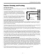
System Cleaning and Flushing procedures
.
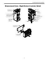
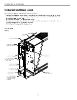
Pipe Locations
Figure 2
CONSOLE
CABINET
CONSOLE
CHASSIS
CONDENSATE
DRAIN LOCATION
WATER CONNECTIONS
TARGET AREA FOR
WALL PENETRATION
FUSED ELECTRICAL
DISCONNECT(OPTIONAL)
5˝ x 8˝ AREA APPOX. 1/2˝
FROM EDGE OF CHASSIS
1˝ FROM FRONT EDGE
OF CABINET
5˝
8˝
TARGET AREA FOR
FLOOR PENETRATION
CABINET EXTENDS
TO THIS POINT
5˝ x 8˝ AREA APPOX. 1/2˝
FROM EDGE OF CHASSIS
3˝ FROM FLOOR
24V ACCESSORY
ELECTRICAL
JUNCTION BOX

