background image

SA-Series

SA SERIES ENERGY RECOVERY CORE ARRAY

Installation, Operation and Maintenance Manual

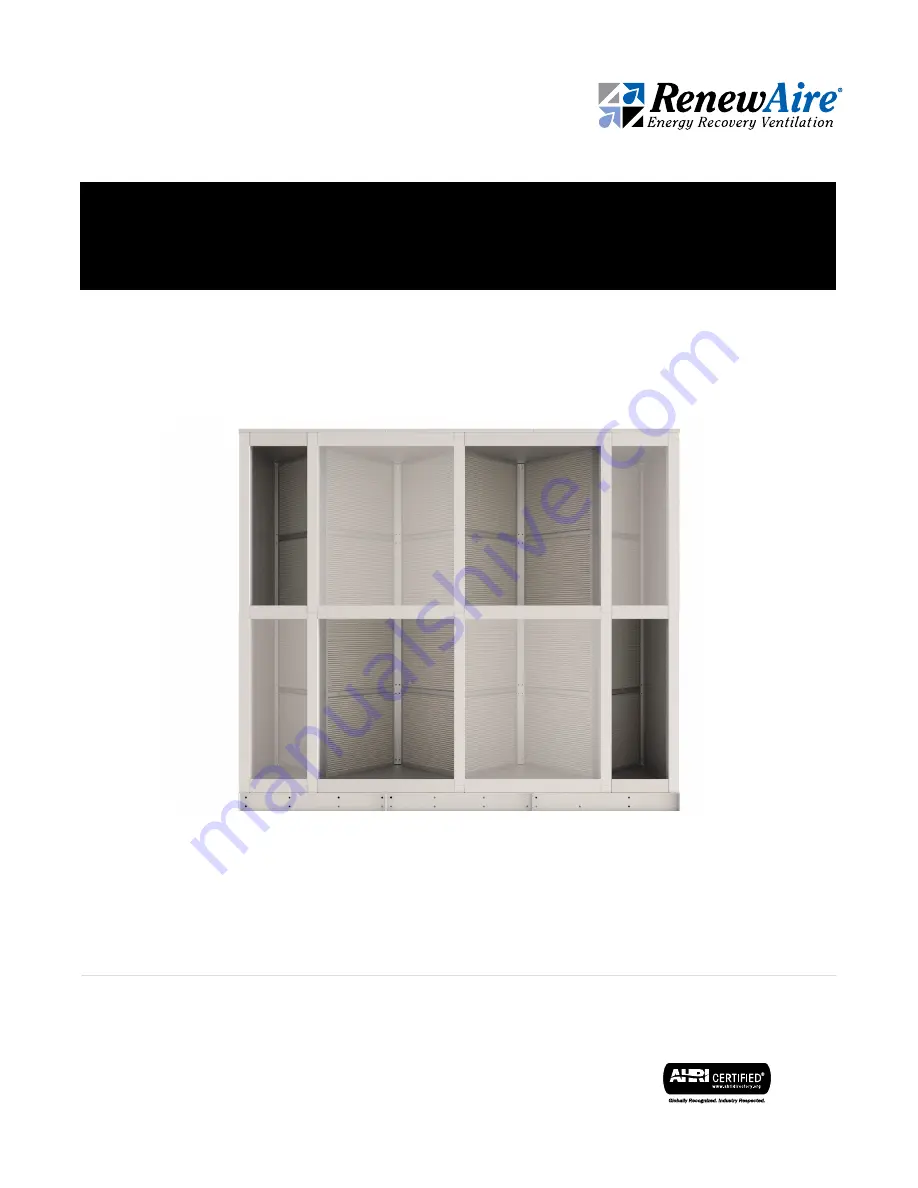
Model SA4H3W Shown

Summary of Contents for RenewAire SA Series

Page 1: ...SA Series SA SERIES ENERGY RECOVERY CORE ARRAY Installation Operation and Maintenance Manual Model SA4H3W Shown ...

Page 2: ...is not to be moved after assembly CAUTION Air ducts connecting this Energy Recovery Core Array to the Occupied Space must be installed in accordance with the Standards of the National Fire Protection Agency for the instal lation of Air Conditioning and Ventilating Systems Pamphlet No 90A and Warm Air Heating and Air Conditioning Systems Pamphlet No 90B IMPORTANT RISK OF DAMAGE TO ENTHALPIC CORES E...

Page 3: ...this information will be needed Serial Number SO Unit Option Code NOTE This information is for purposes of identifying the unit specific option data as needed from the option code UNIT RECORDS TYPICAL SA SERIES UNIT LABEL UNIT INFORMATION OWNER INFORMATION NOTE This page is to be completed by the installing contractor The completed document is to be turned over to the owner after start up NOTICE T...

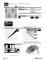
Page 4: ...rossflow SAIN Parallel flow Can be configured on site Available as shown AIRFLOW ORIENTATION INDOOR UNIT Stackable Array NEW When parallel flow airflow orientation is used flow is not optimally distributed to every exchanger and performance is slightly reduced In this case the sensible and latent effective ness must be derated by the amount shown in the EFFECTIVENESS DERATE chart This derate is au...

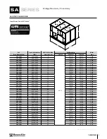
Page 5: ... 666 SA6H8W 12 000 52 800 48 260 1 2 125 1 2 5 282 SA7H3W 5 250 23 100 21 97 3 4 145 3 8 2 483 SA7H4W 7 000 30 800 28 130 1 4 145 3 8 3 174 SA7H5W 8 750 38 500 35 162 7 8 145 3 8 3 864 SA7H6W 10 500 46 200 42 195 3 8 145 3 8 4 554 SA7H7W 12 250 53 900 49 228 145 3 8 5 244 SA7H8W 14 000 61 600 56 260 1 2 145 3 8 5 934 SA8H3W 6 000 26 400 24 97 3 4 165 1 4 2 765 SA8H4W 8 000 35 200 32 130 1 4 165 1 ...

Page 6: ...re 5 3 1 Bottom Middle Core 17 Figure 5 3 2 Top Core 17 Figure 5 3 3 1 2 Core Support Bracket 17 Figure 5 3 4 Connector Bracket 17 Figure 5 3 5 Core Joining Strap 17 Figure 5 3 6 Wall 17 Figure 5 3 7 Post 17 Figure 5 3 8 Insulated Plenum Divider 17 Figure 5 3 9 1 2 Core Face Plate Panel 17 Figure 5 3 10 2 Core Support Bracket 17 Figure 5 3 11 2 Core Face Plate Panel 17 Figure 5 3 12 Roof Assembly ...

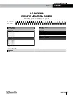
Page 7: ...20 21 22 23 24 25 Digits 1 2 Series Digits 8 9 Location SA Stackable Array IN Indoor Digits 3 4 Array Core Height Digits 10 23 Unused 3H 3 Core Height Unused 4H 4 Core Height 5H 5 Core Height Digit 24 Other Options 6H 6 Core Height K Knockdown 7H 7 Core Height X Custom Unit 8H 8 Core Height Digit 25 Safety Listing Digits 5 6 Array Core Width N Non Listed 3W 3 Core Width 4W 4 Core Width 5W 5 Core W...

Page 8: ...ms never mix but the energy both sensible and latent is transferred from the exhaust air and supplied to the incoming outdoor air The enthalpic cores are stacked into columns and then sheet metal panels are installed to form plenums so that Exhaust Air EA and Outdoor Air OA can be kept separate The only maintenance required for the module is annual vacuuming of the inlet sides of the enthalpic cor...

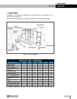
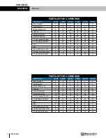
Page 9: ...DESCRIPTION 3 WIDE 4 WIDE 5 WIDE 6 WIDE 7 WIDE 8 WIDE Base Assembly 3 4 5 6 7 8 Roof Assembly 3 4 5 6 7 8 Bottom Middle Core 6 8 10 12 14 16 Top Core 3 4 5 6 7 8 Connector Bracket 4 6 8 10 12 14 Core Joining Strap 6 9 12 15 18 21 1 2 Core Support Bracket 12 12 12 12 12 12 2 Core Support Bracket 12 18 24 30 36 42 Post 10 12 14 16 18 20 Wall 4 4 4 4 4 4 Insulated Plenum Divider 6 8 10 12 14 16 1 2 C...

Page 10: ...lated Plenum Divider 6 8 10 12 14 16 1 2 Core Face Plate Panel 4 4 4 4 4 4 2 Core Face Plate Panel 4 6 8 10 12 14 PARTS LIST FOR 5 CORES HIGH DESCRIPTION 3 WIDE 4 WIDE 5 WIDE 6 WIDE 7 WIDE 8 WIDE Base Assembly 3 4 5 6 7 8 Roof Assembly 3 4 5 6 7 8 Bottom Middle Core 12 16 20 24 28 32 Top Core 3 4 5 6 7 8 Connector Bracket 8 12 16 20 24 28 Core Joining Strap 10 15 20 25 30 35 1 2 Core Support Brack...

Page 11: ...ated Plenum Divider 12 16 20 24 28 32 1 2 Core Face Plate Panel 4 4 4 4 4 4 2 Core Face Plate Panel 4 6 8 10 12 14 PARTS LIST FOR 7 CORES HIGH DESCRIPTION 3 WIDE 4 WIDE 5 WIDE 6 WIDE 7 WIDE 8 WIDE Base Assembly 3 4 5 6 7 8 Roof Assembly 3 4 5 6 7 8 Bottom Middle Core 18 24 30 36 42 48 Top Core 3 4 5 6 7 8 Connector Bracket 12 18 24 30 36 42 Core Joining Strap 14 21 28 35 42 49 1 2 Core Support Bra...

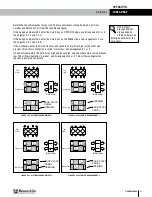
Page 12: ...nd all other plenums are 2 Core wide All plenums extend full height from the floor of the Core Array to the ceiling panels The exterior surface of each plenum has sheet metal panels that cover half the frontal surface of the plenum These panels provide rigidity to the structure and provide a means of access to perform annual maintenance of the cores Every adjoining plenum has an opposite direction...

Page 13: ... 2 2 End View Front View ARRANGEMENT 1 OPPOSITE SIDE ENTRIES CROSS AIRFLOWS 2 2 1 1 Back View View Top FACE PLATE PANEL 1 OUT 2 IN 1 OUT 2 IN 1 IN 1 IN 2 OUT 2 OUT OPENING End View 1 1 1 1 2 2 2 2 1 1 2 2 ARRANGEMENT 2 SAME SIDE ENTRIES CROSS AIRFLOWS View Top Back View Front View 1 IN 1 IN 2 IN 2 IN 1 OUT 1 OUT 2 OUT 2 OUT OPENING FACE PLATE PANEL End View 1 View Top 1 2 1 1 2 2 2 1 1 2 2 ARRANGE...

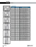
Page 14: ...195 3 8 W x 64 1 2 D 5 7 105 3 8 H x 228 W x 64 1 2 D 5 8 105 3 8 H x 260 1 2 W x 64 1 2 D 6 3 125 1 2 H x 97 3 4 W x 64 1 2 D 6 4 125 1 2 H x 130 1 4 W x 64 1 2 D 6 5 125 1 2 H x 162 7 8 W x 64 1 2 D 6 6 125 1 2 H x 195 3 8 W x 64 1 2 D 6 7 125 1 2 H x 228 W x 64 1 2 D 6 8 125 1 2 H x 260 1 2 W x 64 1 2 D 7 3 145 3 8 H x 97 3 4 W x 64 1 2 D 7 4 145 3 8 H x 130 1 4 W x 64 1 2 D 7 5 145 3 8 H x 162...

Page 15: ...semblies See parts lists on pages 9 12 and 16 to confirm quantities needed to build the unit size ordered NOTE Cores must be protected from weather and other damage until they are installed NOTE Ladders MUST NOT be leaned against the core assemblies nor against the Core Array structure either during or after assembly of the Core Array 4 2 HANDLING AND STORAGE Palletized can be handled with a forkl...

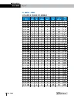
Page 16: ...100 120 729 SA5H4WJIN 6 6 12 124 124 128 924 SA5H5WJIN 8 8 16 148 148 136 1119 SA5H6WJIN 10 10 20 172 172 144 1314 SA5H7WJIN 12 12 24 196 196 152 1509 SA5H8WJIN 14 14 28 220 220 160 1704 SA6H3WJIN 4 4 8 184 184 272 1123 SA6H4WJIN 6 6 12 216 216 288 1408 SA6H5WJIN 8 8 16 248 248 304 1693 SA6H6WJIN 10 10 20 280 280 320 1978 SA6H7WJIN 12 12 24 312 312 336 2263 SA6H8WJIN 14 14 28 344 344 352 2548 SA7H...

Page 17: ...0 627 4499 support renewaire com www renewaire com 800 627 4499 support renewaire com FIGURE 5 3 3 1 2 CORE SUPPORT BRACKET FIGURE 5 3 10 2 CORE SUPPORT BRACKET www renewaire com 800 627 4499 support renewaire com FIGURE 5 3 12 ROOF ASSEMBLY 5 2 TOOLS NEEDED FOR ASSEMBLY Battery Drill Driver 2 Phillips or Square Drive Drift Pins and C clamp Pliers 2 Dead Blow Hammer 4 Level 7 16 and 9 16 Wrenches ...

Page 18: ...which may cause the base modules to rock Begin stacking the Bottom Middle Cores on the base modules These cores have horizonal joining straps installed on the top of the cores All cores are omni directional and may be turned any direction Stack two cores that have the horizontal joining straps on them on each base module See Figure 5 4 1 www renewaire com 800 627 4499 support renewaire com FIGURE ...

Page 19: ... only See Figure 5 4 3 FIGURE 5 4 2 ATTACH CORES TO BASES FIGURE 5 4 3 INSTALL CORE JOINING STRAPS AND CONNECTOR BRACKETS www renewaire com 800 627 4499 support renewaire com When the cores are stacked 2 rows high install 8 x 1 2 Screws through the alignment angles on the floor of the Base Assemblies into the cores themselves Secure all 4 bottom edges of all installed cores Install 8 x 1 2 screws ...

Page 20: ...17 For SA Series unit heights 6H 7H and 8H you will continue stacking the cores later in the assembly process Install Posts at all four corners and at the centerline of each base module where the Insulated Plenum Divider will be located Posts are installed with two 1 4 20 Bolts and Nuts and four Flat Washers See Figure 5 4 4 FIGURE 5 4 4 INSTALL POSTS FIGURE 5 4 5 INSTALL INSULATED PLENUM DIVIDERS...

Page 21: ...499 support renewaire com Install Walls using 8 x 1 2 Screws to secure them to the base and corner posts Use 1 4 20 Bolts two Washers and Nut to secure walls through the cores and second wall See Figure 5 4 6 www renewaire com 800 627 4499 support renewaire com Install 1 2 Core Support Brackets using 8 x 1 2 Screws See Figure 5 4 7 OVERVIEW ...

Page 22: ...de Panels are secured to the rails and posts with 8 x 1 2 Screws See Figure 5 4 9 www renewaire com 800 627 4499 support renewaire com Install 2 Core Support Brackets using 8 x 1 2 Screws See Figure 5 4 8 www renewaire com 800 627 4499 support renewaire com FIGURE 5 4 8 INSTALL 2 CORE SUPPORT BRACKETS FIGURE 5 4 9 INSTALL FACE PLATE PANELS At this point in the assembly if the model core height is ...

Page 23: ...he unit filters must be kept in place to avoid dust dirt and debris from entering the structure A need for filter changes is generally discovered by an automated monitoring system that is part of either a Direct Digital Controller DDC or a Building Management System BMS If there is no pressure drop data that can be used to indicate dirty filters the filters should be inspected monthly If filters l...

Page 24: ...ility derived from innovative design practices expert workmanship and Quick Response Manufacturing QRM As the pioneer of static plate core technology in North America RenewAire is the largest ERV producer in the USA We re committed to sustainable manufacturing and lessening our environmental footprint and to that end our Waunakee WI plant is 100 powered by wind turbines The facility is also one of...

Reviews: