background image

3

II. INTRODUCTION

This booklet contains the installation and operating instructions for your package air con-

ditioner. There are a few precautions that should be taken to derive maximum satisfac-

tion from it. Improper installation can result in unsatisfactory operation or dangerous con-

ditions.
Read this booklet and any instructions packaged with separate equipment required to

make up the system prior to installation. Give this booklet to the owner and explain its

provisions. The owner should retain this booklet for future reference.

III. CHECKING PRODUCT RECEIVED

Upon receiving the unit, inspect it for any damage from shipment. Claims for damage,

either shipping or concealed, should be filed immediately with the shipping company.

Check the unit model number, electrical characteristics, and accessories to determine if

they are correct.

IV. SPECIFICATIONS

A. GENERAL

The Packaged Air Conditioner is available without heat or with 6, 10, 12, 15, 20 or 24

kW electric heat. Cooling capacities of 3, 3

1

2

, 4 and 5 nominal tons of cooling are avail-

able. Units are convertible from end supply and return to bottom supply and return by

relocation of supply and return air access panels. See cover installation detail.
The units are weatherized for mounting outside of the building.
The information on the rating plate is in compliance with the FTC and DOE rating for sin-

gle phase units. The following information is for three phase units which

are not

covered

under the DOE certification program.

1. The efficiency rating of this unit is a product thermal efficiency rating determined

under continuous operating conditions independent of any installed system.

B. MAJOR COMPONENTS

The unit includes a hermetically-sealed refrigerating system (consisting of a compressor,

condenser coil, evaporator coil with thermal expansion valve), a circulation air blower, a

condenser fan, and all necessary internal electrical wiring. The cooling system of these

units is factory-evacuated, charged and performance tested. Refrigerant amount and

type are indicated on rating plate.

C. R-410A REFRIGERANT

All units are factory charged with R-410A refrigerant.

1. Specification of R-410A:

Application: R-410A is not a drop-in replacement for R-22;

equipment designs must

accommodate its higher pressures. It cannot be retrofitted into R-22 units.

Pressure: The pressure of R-410A is approximately 60% (1.6 times) greater than
R-22.

Recovery and recycle equipment, pumps, hoses and the like need to have design

pressure ratings appropriate for R-410A.

Manifold sets need to range up to 800 psig

high-side and 250 psig low-side with a 550 psig low-side retard. Hoses need to have a
service pressure rating of 800 psig. Recovery cylinders need to have a 400 psig service
pressure rating.

DOT 4BA400 or DOT BW400.

Combustibility:

At pressures above 1 atmosphere, mixture of R-410A and air can

become combustible.

R-410A and air should never be mixed in tanks or supply

lines, or be allowed to accumulate in storage tanks. Leak checking should never
be done with a mixture of R-410A and air.

Leak checking can be performed safely

with nitrogen or a mixture of R-410A and nitrogen.

2. Quick Reference Guide For R-410A

• R-410A refrigerant operates at approximately 60% higher pressure (1.6 times) than R-

22. Ensure that servicing equipment is designed to operate with R-410A.

• R-410A refrigerant cylinders are pink.
• R-410A, as with other HFC’s is only compatible with POE oils.
• Vacuum pumps will not remove moisture from POE oil.

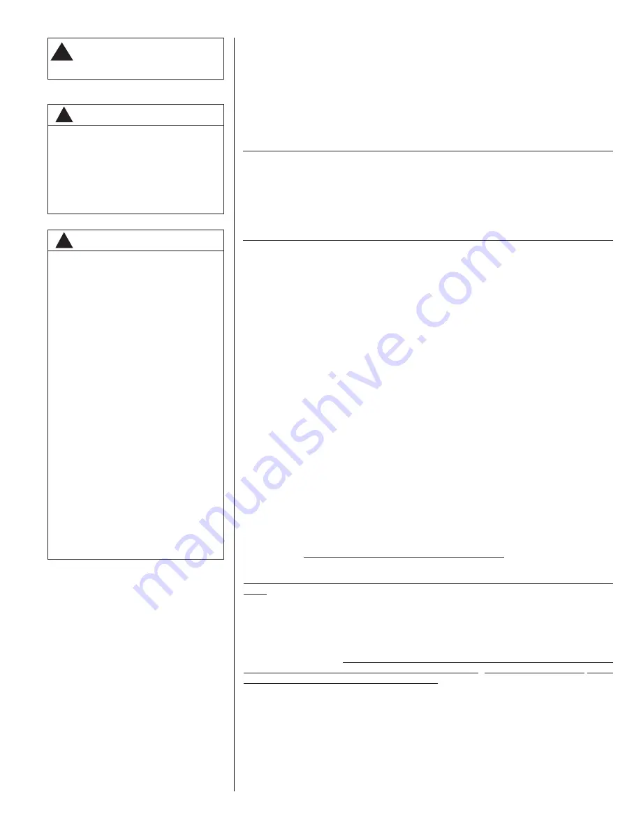
!

WARNING

PROPOSITION 65: THIS APPLI-
ANCE CONTAINS FIBERGLASS
INSULATION. RESPIRABLE
PARTICLES OF FIBERGLASS
ARE KNOWN TO THE STATE
OF CALIFORNIA TO CAUSE
CANCER.

.

!

WARNING

THE MANUFACTURER’S WAR-
RANTY DOES NOT COVER ANY
DAMAGE OR DEFECT TO THE
AIR CONDITIONER CAUSED BY
THE ATTACHMENT OR USE OF
ANY COMPONENTS, ACCES-
SORIES OR DEVICES (OTHER
THAN THOSE AUTHORIZED BY
THE MANUFACTURER) INTO,
ONTO OR IN CONJUNCTION
WITH THE AIR CONDITIONER.
YOU SHOULD BE AWARE THAT
THE USE OF UNAUTHORIZED
COMPONENTS, ACCESSORIES
OR DEVICES MAY ADVERSELY
AFFECT THE OPERATION OF
THE AIR CONDITIONER AND
MAY ALSO ENDANGER LIFE
AND PROPERTY. THE MANU-
FACTURER DISCLAIMS ANY
RESPONSIBILITY FOR SUCH
LOSS OR INJURY RESULTING
FROM THE USE OF SUCH
UNAUTHORIZED COMPO-
NENTS, ACCESSORIES OR
DEVICES.

Recognize this symbol as an indi-

cation of Important Safety

Information!

!

Summary of Contents for RLNL-C 13 SEER Series

Page 1: ...ckage Air Conditioners Featuring Industry Standard R 410A Refrigerant RLNL C 13 SEER 3 5 TONS SERIES RLPL C 14 SEER 3 5 TONS SERIES INDICATES METRIC CONVERSION 92 23577 103 01 SUPERSEDES 92 23577 103 00 14 SEER ONLY ISO 9001 2008 ...

Page 2: ...top Installation 8 VII Ductwork 9 VIII Filters 10 IX Conversion Procedure 10 X Condensate Drain 10 XI Electrical Wiring 11 A Power Wiring 11 B Special Instructions for Power Wiring with Aluminum Conductors 11 C Control Wiring 12 D Internal Wiring 13 E Grounding 13 F Thermostat 13 XII Indoor Air Flow Data 14 XIII Crankcase Heat 14 XIV Pre Start Check 14 XV Startup 14 XVI Operation 15 XVII Auxiliary...

Page 3: ... C R 410A REFRIGERANT All units are factory charged with R 410A refrigerant 1 Specification of R 410A Application R 410A is not a drop in replacement for R 22 equipment designs must accommodate its higher pressures It cannot be retrofitted into R 22 units Pressure The pressure of R 410A is approximately 60 1 6 times greater than R 22 Recovery and recycle equipment pumps hoses and the like need to ...

Page 4: ...l contaminants from industries such as paper mills and petroleum refineries are especially corrosive If the unit is to be installed in an area where contaminants are likely to be a prob lem special attention should be given to the equipment location and exposure 1 Avoid having lawn sprinkler heads spray direction on the unit cabinet 2 In coastal areas locate the unit on the side of the building aw...

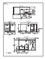
Page 5: ...5 FIGURE 1 UNIT DIMENSIONS BACK VIEW SIDE VIEW FRONT VIEW BOTTOM VIEW ...

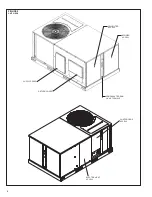
Page 6: ...FIGURE 2 UNIT VIEWS 6 SUPPLY COVER RETURN COVER CONDENSATE DRAIN 3 4 NPT FEMALE BLOWER ACCESS ELECTRIC HEAT ACCESS CONTROL BOX ACCESS COIL FILTER ACCESS ...

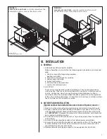
Page 7: ...n Figures 3 and 4 1 Select a location where external water drainage cannot collect around the unit 2 Provide a level concrete slab extending 3 beyond all four sides of the unit The slab should be sufficient above grade to prevent ground water from entering the unit IMPORTANT To prevent transmission of noise or vibration slab should not be connected to building structure 3 The location of the unit ...

Page 8: ... sheet for weight of unit This is very important and user s responsibility 2 For rigging and roofcurb details see Figures 5 and 6 Use field furnished spread ers 3 For roofcurb assembly see Roofcurb Installation Instructions 4 If the roofcurb is not used provisions for disposing of condensate water runoff must be provided 5 The unit should be placed on a solid and level roofcurb or platform of adeq...

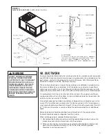
Page 9: ...humidity use a mini mum of 2 of insulation and a vapor barrier Distribution system in attic furred space or crawl space should be insulated with at least 2 of insulation with vapor barrier One half to 1 thickness of insulation is usually sufficient for ductwork inside the air conditioned space Balancing dampers should be provided for each branch duct in the supply system Ductwork should be properl...

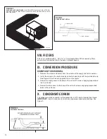
Page 10: ...the covers 3 Secure the supply cover to the base of the unit with 1 screw engaging prepunched tab in unit base 4 Secure the return cover to the base of the unit with screws engaging prepunched holes in the unit base X CONDENSATE DRAIN The condensate drain connection of the evaporator is 3 4 nominal female pipe thread IMPORTANT Install a condensate trap to ensure proper condensate drainage See Figu...

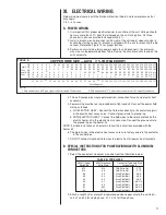
Page 11: ...ired to the contactor in the control box 7 DO NOT connect aluminum field wires to electric heat kit power input terminals B SPECIAL INSTRUCTIONS FOR POWER WIRING WITH ALUMINUM CONDUCTORS 1 Select the equivalent aluminum wire size from the tabulation below 2 Attach a length 6 or more of recommended size copper wire to the unit termi nals L1 and L3 for single phase L1 L2 L3 for three phase TABLE B W...

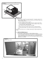
Page 12: ... nuts or split bolt connectors e Coat the entire connection with inhibitor and wrap with electrical insulating tape WARRANTY MAY NOT APPLY IF CONNECTIONS ARE NOT MADE PER INSTRUC TIONS C CONTROL WIRING Class II 1 Low voltage wiring should not be run in conduit with power wiring 2 Control wiring is routed through the 7 8 hole adjacent to the compressor access panel Use a minimum 18 AWG thermostat w...

Page 13: ...ressor access panel If any of the original wire as supplied with the appliance must be replaced the wire gauge and insulation must be the same as original wiring E GROUNDING F THERMOSTAT The thermostat should be mounted on an inside wall about five feet above the floor in a location where it will not be affected by unconditioned air sun or drafts from open doors or other sources READ installation ...

Page 14: ...rant charge using the instructions located on compressor access panel Replace service port caps Service port cores are for system access only and will leak if not tightly capped 9 Turn thermostat system switch to proper mode HEAT or COOl and set thermostat to proper temperature setting Record the following after the unit has run some time A Operating Mode _______________________________ B Discharg...

Page 15: ...uctions with owner XVI OPERATION IMPORTANT The compressor has an internal overload protector Under some condi tions it can take up to 2 hours for this overload to reset Make sure overload has had time to reset before condemning the compressor XVII AUXILIARY HEAT CONTROL SYSTEM OPERATION 1 In the cooling mode the thermostat will on a call for cooling energize the compres sor contactor and the indoo...

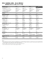
Page 16: ...75 9 5 0 375 9 5 Face Area sq ft sq m 16 91 1 57 16 91 1 57 16 91 1 57 16 91 1 57 Rows FPI FPcm 1 22 9 1 22 9 1 22 9 1 22 9 Indoor Coil Fin Type Corrugated Corrugated Corrugated Corrugated Tube Type Rifled Rifled Rifled Rifled Tube Size in mm 0 375 9 5 0 375 9 5 0 375 9 5 0 375 9 5 Face Area sq ft sq m 5 17 0 48 5 17 0 48 5 17 0 48 5 17 0 48 Rows FPI FPcm 2 17 7 2 17 7 2 17 7 2 17 7 Refrigerant Co...

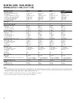
Page 17: ... 9 5 Face Area sq ft sq m 16 91 1 57 16 91 1 57 16 91 1 57 16 91 1 57 Rows FPI FPcm 1 53 22 9 1 53 22 9 1 53 22 9 1 53 22 9 Indoor Coil Fin Type Corrugated Corrugated Corrugated Corrugated Tube Type Rifled Rifled Rifled Rifled Tube Size in mm 0 375 9 5 0 375 9 5 0 375 9 5 0 375 9 5 Face Area sq ft sq m 5 17 0 48 5 17 0 48 5 17 0 48 5 17 0 48 Rows FPI FPcm 3 13 5 3 13 5 3 13 5 3 13 5 Refrigerant Co...

Page 18: ... 375 9 5 0 375 9 5 Face Area sq ft sq m 16 56 1 54 16 56 1 54 16 56 1 54 16 56 1 54 Rows FPI FPcm 2 22 9 2 22 9 2 22 9 2 22 9 Indoor Coil Fin Type Corrugated Corrugated Corrugated Corrugated Tube Type Rifled Rifled Rifled Rifled Tube Size in mm 0 375 9 5 0 375 9 5 0 375 9 5 0 375 9 5 Face Area sq ft sq m 5 17 0 48 5 17 0 48 5 17 0 48 5 17 0 48 Rows FPI FPcm 3 15 6 3 15 6 3 15 6 3 15 6 Refrigerant ...

Page 19: ... 375 9 5 0 375 9 5 Face Area sq ft sq m 16 56 1 54 16 56 1 54 16 56 1 54 16 56 1 54 Rows FPI FPcm 2 22 9 2 22 9 2 22 9 2 22 9 Indoor Coil Fin Type Corrugated Corrugated Corrugated Corrugated Tube Type Rifled Rifled Rifled Rifled Tube Size in mm 0 375 9 5 0 375 9 5 0 375 9 5 0 375 9 5 Face Area sq ft sq m 5 17 0 48 5 17 0 48 5 17 0 48 5 17 0 48 Rows FPI FPcm 3 15 6 3 15 6 3 15 6 3 15 6 Refrigerant ...

Page 20: ...75 9 5 0 375 9 5 Face Area sq ft sq m 16 91 1 57 16 91 1 57 16 91 1 57 16 91 1 57 Rows FPI FPcm 1 22 9 1 22 9 1 22 9 1 22 9 Indoor Coil Fin Type Corrugated Corrugated Corrugated Corrugated Tube Type Rifled Rifled Rifled Rifled Tube Size in mm 0 375 9 5 0 375 9 5 0 375 9 5 0 375 9 5 Face Area sq ft sq m 5 17 0 48 5 17 0 48 5 17 0 48 5 17 0 48 Rows FPI FPcm 2 17 7 2 17 7 2 17 7 2 17 7 Refrigerant Co...

Page 21: ... 5 Face Area sq ft sq m 16 91 1 57 16 91 1 57 16 91 1 57 16 91 1 57 Rows FPI FPcm 1 53 22 9 1 53 22 9 1 53 22 9 1 53 22 9 Indoor Coil Fin Type Corrugated Corrugated Corrugated Corrugated Tube Type Rifled Rifled Rifled Rifled Tube Size in mm 0 375 9 5 0 375 9 5 0 375 9 5 0 375 9 5 Face Area sq ft sq m 5 17 0 48 5 17 0 48 5 17 0 48 5 17 0 48 Rows FPI FPcm 3 13 5 3 13 5 3 13 5 3 13 5 Refrigerant Cont...

Page 22: ...75 9 5 0 375 9 5 Face Area sq ft sq m 16 56 1 54 16 56 1 54 16 56 1 54 16 56 1 54 Rows FPI FPcm 2 22 9 2 22 9 2 22 9 2 22 9 Indoor Coil Fin Type Corrugated Corrugated Corrugated Corrugated Tube Type Rifled Rifled Rifled Rifled Tube Size in mm 0 375 9 5 0 375 9 5 0 375 9 5 0 375 9 5 Face Area sq ft sq m 5 17 0 48 5 17 0 48 5 17 0 48 5 17 0 48 Rows FPI FPcm 3 15 6 3 15 6 3 15 6 3 15 6 Refrigerant Co...

Page 23: ... 375 9 5 0 375 9 5 Face Area sq ft sq m 16 56 1 54 16 56 1 54 16 56 1 54 16 56 1 54 Rows FPI FPcm 2 22 9 2 22 9 2 22 9 2 22 9 Indoor Coil Fin Type Corrugated Corrugated Corrugated Corrugated Tube Type Rifled Rifled Rifled Rifled Tube Size in mm 0 375 9 5 0 375 9 5 0 375 9 5 0 375 9 5 Face Area sq ft sq m 5 17 0 48 5 17 0 48 5 17 0 48 5 17 0 48 Rows FPI FPcm 3 15 6 3 15 6 3 15 6 3 15 6 Refrigerant ...

Page 24: ...1 3 1 3 1 3 1 3 1 3 1 3 1 5 1 5 1 5 1 5 1 1 1 5 1 5 1 5 1 5 1 1 3 3 3 3 1 9 1 9 3 3 3 3 1 9 1 9 1 1 1 1 1 1 1 1 208 230 208 230 460 460 208 230 208 230 460 460 3 3 3 3 3 3 3 3 1 2 3 4 1 2 3 4 1 2 3 4 1 2 3 4 2 8 2 8 3 4 3 4 1 4 1 6 2 8 2 8 3 4 3 4 1 4 1 6 11 3 11 3 16 8 16 8 6 2 8 4 11 3 11 3 16 8 16 8 6 2 8 4 Unit Information Compressor Motor Condenser Motor Evaporator Fan ELECTRICAL DATA RLNL SE...

Page 25: ... 3 1 3 1 3 1 3 1 5 1 5 1 5 1 5 1 1 2 2 2 2 2 2 2 2 1 1 3 3 3 3 1 9 1 9 4 9 4 9 4 9 4 9 1 9 1 9 1 1 1 1 1 1 1 1 208 230 208 230 460 460 208 230 208 230 460 460 3 3 3 3 3 3 3 3 1 2 3 4 1 2 3 4 3 4 1 3 4 1 2 8 2 8 3 4 3 4 1 4 1 6 3 4 3 4 3 8 3 8 1 6 1 9 11 3 11 3 16 8 16 8 6 2 8 4 16 8 16 8 24 24 8 4 12 Unit Information Compressor Motor Condenser Motor Evaporator Fan ELECTRICAL DATA RLNL SERIES C048C...

Page 26: ... 3 1 3 1 3 1 3 1 5 1 5 1 5 1 5 1 1 1 5 1 5 1 5 1 5 1 1 3 3 3 3 1 9 1 9 3 3 3 3 1 9 1 9 1 1 1 1 1 1 1 1 208 230 208 230 460 460 208 230 208 230 460 460 3 3 3 3 3 3 3 3 1 2 3 4 1 2 3 4 1 2 3 4 1 2 3 4 2 8 2 8 2 8 2 8 1 4 1 6 2 8 2 8 3 4 3 4 1 4 1 6 11 3 11 3 16 8 16 8 6 2 8 4 11 3 11 3 16 8 16 8 6 2 8 4 Unit Information Compressor Motor Condenser Motor Evaporator Fan ELECTRICAL DATA RLPL SERIES C036...

Page 27: ...1 3 1 3 1 5 1 5 1 5 1 5 1 1 2 2 2 2 2 2 2 2 1 1 3 3 3 3 1 9 1 9 4 9 4 9 4 9 4 9 1 9 1 9 1 1 1 1 1 1 1 1 208 230 208 230 460 460 208 230 208 230 460 460 3 3 3 3 3 3 3 3 1 2 3 4 1 2 3 4 3 4 1 3 4 1 2 8 2 8 2 8 2 8 1 4 1 6 3 4 3 4 3 8 3 8 1 6 1 9 11 3 11 3 16 8 16 8 6 2 8 4 16 8 16 8 24 24 8 4 12 Unit Information Compressor Motor Condenser Motor Evaporator Fan ELECTRICAL DATA RLPL SERIES C036CL C036C...

Page 28: ...0 1225 1245 WATTS 445 465 485 520 565 615 660 730 800 870 RPM 1080 1100 1115 1145 1165 1195 1220 1245 1265 1290 WATTS 470 500 540 560 590 645 720 780 830 910 RPM 1140 1160 1180 1200 1220 1230 1255 1280 1295 1310 WATTS 510 530 540 600 645 685 740 800 875 930 RPM 1190 1210 1230 1250 1260 1280 1295 1325 1350 WATTS 540 560 600 630 675 725 785 840 910 RPM 1235 1255 1270 1285 1305 1325 1350 1365 WATTS 5...

Page 29: ...e L M and N drives respectively NOTE Factory sheave settings are shown in bold print M L RPM 780 800 830 860 895 940 970 WATTS 455 485 550 615 680 755 825 RPM 780 795 815 850 880 915 945 975 1015 WATTS 390 450 470 530 605 655 735 795 880 RPM 780 795 805 840 870 895 930 955 995 1015 1040 WATTS 370 405 425 490 540 590 655 705 780 830 925 RPM 815 840 870 895 915 945 970 1005 1030 1065 1100 WATTS 385 ...

Page 30: ...57 644 898 695 939 739 981 777 1022 811 1044 848 1073 916 1103 980 1134 1041 1168 1099 1202 1154 1237 1207 1270 1258 1300 1307 2100 991 845 653 885 720 927 771 968 814 1009 852 1035 869 1064 943 1093 1011 1123 1075 1154 1136 1187 1194 1222 1249 1256 1302 1290 1353 2200 1038 873 734 913 801 955 852 996 896 1037 934 1057 971 1086 1044 1115 1113 1145 1177 1176 1238 1210 1295 1244 1350 1279 1403 2300 ...

Page 31: ... 50 60 No Heat 22 22 25 30 25 30 22 22 25 30 25 30 A06C 1 4 2 5 6 14 33 19 1 11 7 13 5 22 22 25 30 25 30 15 17 15 20 A10C 1 7 2 9 6 24 56 32 75 20 23 1 29 33 30 30 35 35 25 29 25 30 A12C 1 8 4 11 2 28 66 38 21 23 4 27 33 38 35 35 40 40 30 34 30 35 A15C 1 10 8 14 4 36 84 49 13 30 1 34 7 42 47 45 45 50 50 38 44 40 45 A20C 1 14 4 19 2 49 13 65 5 40 46 3 54 62 60 60 70 70 50 58 50 60 No Heat 22 22 25 ...

Page 32: ... 60 No Heat 22 22 30 35 30 35 22 22 30 35 30 35 A06C 1 4 2 5 6 14 33 19 1 11 7 13 5 22 22 30 35 30 35 15 17 15 20 A10C 1 7 2 9 6 24 56 32 75 20 23 1 30 34 30 35 35 35 25 29 25 30 A12C 1 8 4 11 2 28 66 38 21 23 4 27 34 38 35 35 40 40 30 34 30 35 A15C 1 10 8 14 4 36 84 49 13 30 1 34 7 42 48 45 45 50 50 38 44 40 45 A20C 1 14 4 19 2 49 13 65 5 40 46 3 55 63 60 60 70 70 50 58 50 60 No Heat 23 23 30 35 ...

Page 33: ...6D 1 5 6 19 1 6 8 11 15 15 9 15 A10D 1 9 6 32 75 11 6 17 20 20 15 15 A12D 1 11 2 38 21 13 5 19 20 20 17 20 A15D 1 14 4 49 13 17 4 24 25 25 22 25 A20D 1 19 2 65 5 23 3 31 35 35 30 30 No Heat 10 15 15 10 15 15 A06D 1 5 6 19 1 6 8 11 15 15 9 15 A10D 1 9 6 32 75 11 6 17 20 20 15 15 A12D 1 11 2 38 21 13 5 19 20 20 17 20 A15D 1 14 4 49 13 17 4 24 25 25 22 25 A20D 1 19 2 65 5 23 3 31 35 35 30 30 No Heat ...

Page 34: ...6D 1 5 6 19 1 6 8 11 15 15 9 15 A10D 1 9 6 32 75 11 6 17 20 20 15 15 A12D 1 11 2 38 21 13 5 19 20 20 17 20 A15D 1 14 4 49 13 17 4 24 25 25 22 25 A20D 1 19 2 65 5 23 3 32 35 35 30 30 No Heat 11 15 15 11 15 15 A06D 1 5 6 19 1 6 8 11 15 15 9 15 A10D 1 9 6 32 75 11 6 17 20 20 15 15 A12D 1 11 2 38 21 13 5 19 20 20 17 20 A15D 1 14 4 49 13 17 4 24 25 25 22 25 A20D 1 19 2 65 5 23 3 32 35 35 30 30 No Heat ...

Page 35: ... 46 3 54 62 60 60 70 70 50 58 50 60 No Heat 22 22 25 30 25 30 22 22 25 30 25 30 A06C 1 4 2 5 6 14 33 19 1 11 7 13 5 22 22 25 30 25 30 15 17 15 20 A10C 1 7 2 9 6 24 56 32 75 20 23 1 29 33 30 30 35 35 25 29 25 30 A12C 1 8 4 11 2 28 66 38 21 23 4 27 33 38 35 35 40 40 30 34 30 35 A15C 1 10 8 14 4 36 84 49 13 30 1 34 7 42 47 45 45 50 50 38 44 40 45 A20C 1 14 4 19 2 49 13 65 5 40 46 3 54 62 60 60 70 70 ...

Page 36: ... 60 No Heat 22 22 30 35 30 35 22 22 30 35 30 35 A06C 1 4 2 5 6 14 33 19 1 11 7 13 5 22 22 30 35 30 35 15 17 15 20 A10C 1 7 2 9 6 24 56 32 75 20 23 1 30 34 30 35 35 35 25 29 25 30 A12C 1 8 4 11 2 28 66 38 21 23 4 27 34 38 35 35 40 40 30 34 30 35 A15C 1 10 8 14 4 36 84 49 13 30 1 34 7 42 48 45 45 50 50 38 44 40 45 A20C 1 14 4 19 2 49 13 65 5 40 46 3 55 63 60 60 70 70 50 58 50 60 No Heat 23 23 30 35 ...

Page 37: ...6D 1 5 6 19 1 6 8 11 15 15 9 15 A10D 1 9 6 32 75 11 6 17 20 20 15 15 A12D 1 11 2 38 21 13 5 19 20 20 17 20 A15D 1 14 4 49 13 17 4 24 25 25 22 25 A20D 1 19 2 65 5 23 3 31 35 35 30 30 No Heat 10 15 15 10 15 15 A06D 1 5 6 19 1 6 8 11 15 15 9 15 A10D 1 9 6 32 75 11 6 17 20 20 15 15 A12D 1 11 2 38 21 13 5 19 20 20 17 20 A15D 1 14 4 49 13 17 4 24 25 25 22 25 A20D 1 19 2 65 5 23 3 31 35 35 30 30 No Heat ...

Page 38: ... A06D 1 5 6 19 1 6 8 11 15 15 9 15 A10D 1 9 6 32 75 11 6 17 20 20 15 15 A12D 1 11 2 38 21 13 5 19 20 20 17 20 A15D 1 14 4 49 13 17 4 24 25 25 22 25 A20D 1 19 2 65 5 23 3 32 35 35 30 30 No Heat 11 15 15 11 15 15 A06D 1 5 6 19 1 6 8 11 15 15 9 15 A10D 1 9 6 32 75 11 6 17 20 20 15 15 A12D 1 11 2 38 21 13 5 19 20 20 17 20 A15D 1 14 4 49 13 17 4 24 25 25 22 25 A20D 1 19 2 65 5 23 3 32 35 35 30 30 No He...

Page 39: ...39 FIGURE 14 WIRING DIAGRAM ...

Page 40: ...175 200 225 250 275 300 325 350 375 400 425 450 475 500 525 120 125 130 135 140 145 150 155 160 165 170 55 65 75 85 95 105 115 92 102259 01 01 3 TON AIR CONDITIONER 13 14 SEER 40 ...

Page 41: ...3 5 TON AIR CONDITIONER 13 14 SEER 41 ...

Page 42: ...4 TON AIR CONDITIONER 13 14 SEER 42 ...

Page 43: ...5 TON AIR CONDITIONER 13 SEER 43 ...

Page 44: ... 00 SYSTEM CHARGE CHART REFRIGERANT 410A 5 TON 14 SEER 55 65 75 85 95 105 115 175 200 225 250 275 300 325 350 375 400 425 450 475 500 525 120 125 130 135 140 145 150 155 160 165 170 5 TON AIR CONDITIONER 14 SEER 44 ...

Page 45: ...nit is operating Defective overload protector Replace check for correct voltage Refrigerant undercharge Add refrigerant Registers sweat Low evaporator airflow Increase speed of blower or reduce restriction replace air filter High head low vapor pressures Restriction in liquid line expansion device or filter drier Remove or replace defective component Flow check piston size too small Change to corr...

Page 46: ...46 ...

Page 47: ...47 ...

Page 48: ...48 CM 0610 ...

Reviews: