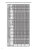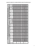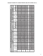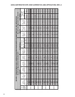
AUXILIARY HEATER KITS CHARACTERISTICS AND APPLICATION–RLPL-C
4
8
0
V
O
L
T
,
T
H
R
E
E
P
H
A
S
E
,
6
0
H
Z
,
A
U
X
IL
IA
R
Y
E
L
E
C
T
R
IC
H
E
A
T
E
R
K
IT
S
C
H
A
R
A
C
T
E
R
IS
T
IC
S
A
N
D
A
P
P
L
IC
A
T
IO
N
S
in
g
le
P
o
w
e
r
S
u
p
p
ly
F
o
r
B
o
th
U
n
it
A
n
d
H
e
a
te
r
K
it
S
e
p
a
ra
te
P
o
w
e
r
S
u
p
p
ly
F
o
r
U
n
it
A
n
d
H
e
a
te
r
K
it
A
ir
C
o
n
d
it
io
n
e
r
H
e
a
te
r
K
it
H
e
a
te
r
K
it
Un
it
M
od
el
Nu
m
be
r
RL
PL
-
RX
JJ
-
He
at
er
Ki
t
No
m
in
al
kW
No
.o
f
Se
qu
en
ce
St
ep
s
Ra
te
d
He
at
er
kW
@
20
8/
24
0
V
He
at
er
KB
TU
/H
r@
20
8/
24
0
V
He
at
er
Am
p.
@
20
8/
24
0
V
Un
it
M
in
.C
kt
Am
pa
cit
y
@
20
8/
24
0V
M
in
/M
ax
@
20
8
V
M
in
/M
ax
@
24
0
V
O
ve
rC
ur
re
nt
Pr
ot
ec
tiv
e
De
vic
e
Si
ze
M
in
.C
kt
.
Am
pa
cit
y
20
8/
24
0
V
M
ax
.F
us
e
Si
ze
20
8/
24
0
V
M
in
.C
kt
.
Am
pa
cit
y
20
8/
24
0
V
M
in
/M
ax
@
20
8
V
M
in
/M
ax
@
24
0
V
O
ve
rC
ur
re
nt
Pr
ot
ec
tiv
e
De
vic
e
Si
ze
No
He
at
—
—
—
—
10
15
/1
5
—
—
—
10
15
/1
5
—
A0
6D
1
5.
6
19
.1
6.
8
11
15
/1
5
—
9
15
—
—
—
A1
0D
1
9.
6
32
.7
5
11
.6
17
20
/2
0
—
15
15
—
—
—
A1
2D
1
11
.2
38
.2
1
13
.5
19
20
/2
0
—
17
20
—
—
—
A1
5D
1
14
.4
49
.1
3
17
.4
24
25
/2
5
—
22
25
—
—
—
A2
0D
1
19
.2
65
.5
23
.3
31
35
/3
5
—
30
30
—
—
—
No
He
at
—
—
—
—
11
15
/1
5
—
—
—
11
15
/1
5
—
A0
6D
1
5.
6
19
.1
6.
8
11
15
/1
5
—
9
15
—
—
—
A1
0D
1
9.
6
32
.7
5
11
.6
17
20
/2
0
—
15
15
—
—
—
A1
2D
1
11
.2
38
.2
1
13
.5
19
20
/2
0
—
17
20
—
—
—
A1
5D
1
14
.4
49
.1
3
17
.4
24
25
/2
5
—
22
25
—
—
—
A2
0D
1
19
.2
65
.5
23
.3
31
35
/3
5
—
30
30
—
—
—
No
He
at
—
—
—
—
13
15
/2
0
—
—
—
13
15
/2
0
—
A0
6D
1
5.
6
19
.1
6.
8
13
15
/2
0
—
9
15
—
—
—
A1
0D
1
9.
6
32
.7
5
11
.6
17
20
/2
0
—
15
15
—
—
—
A1
2D
1
11
.2
38
.2
1
13
.5
19
20
/2
0
—
17
20
—
—
—
A1
5D
1
14
.4
49
.1
3
17
.4
24
25
/2
5
—
22
25
—
—
—
A2
0D
1
19
.2
65
.5
23
.3
32
35
/3
5
—
30
30
—
—
—
A2
4D
1
24
81
.8
8
28
.9
39
40
/4
0
—
37
40
—
—
—
C0
36
DL
C0
42
DL
C0
48
DL
C0
60
DL
A
ir
C
o
n
d
it
io
n
e
r
37
Summary of Contents for RLNL-C 13 SEER Series
Page 5: ...5 FIGURE 1 UNIT DIMENSIONS BACK VIEW SIDE VIEW FRONT VIEW BOTTOM VIEW ...
Page 39: ...39 FIGURE 14 WIRING DIAGRAM ...
Page 41: ...3 5 TON AIR CONDITIONER 13 14 SEER 41 ...
Page 42: ...4 TON AIR CONDITIONER 13 14 SEER 42 ...
Page 43: ...5 TON AIR CONDITIONER 13 SEER 43 ...
Page 46: ...46 ...
Page 47: ...47 ...
Page 48: ...48 CM 0610 ...


