background image


----EN

EN

EN

EN----


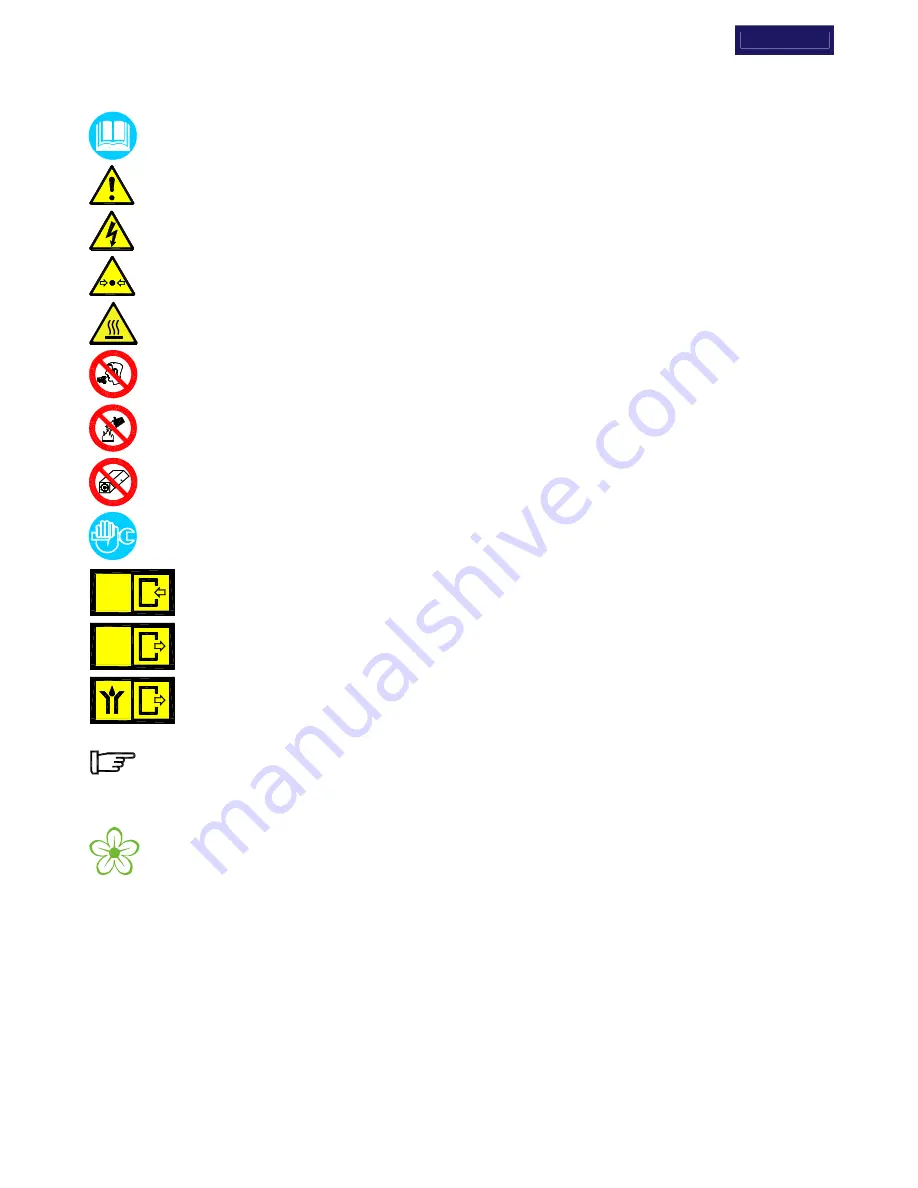
1.1 DEFINITION OF THE CONVENTIONAL SIGNS USED IN THIS MANUAL 


Carefully read instruction manual before attempting any service or maintenance procedures on the 
dryer. 


Caution  warning  sign.  Risk  of  danger  or  possibility  of  damage  to  equipment, if related text is not 
followed properly. 


Electrical hazard. Warning message indicates practices or procedures that could result in personal 
injury or fatality if not followed correctly. 


Danger hazard. Part or system under pressure. 


Danger hazard. High temperature conditions exist during operation of system. Avoid contact until 
system or component has dissipated heat. 


Danger  hazard.  Treated  air  is  not  suitable  for  breathing  purposes;  serious  injury  or  fatality  may 
result if precautions are not followed. 


Danger  hazard:  In  case  of  fire,  use  an  approved  fire  extinguisher,  water  is  not  an  acceptable 
means in cases of fire. 


Danger hazard. Do not operate equipment with panels removed. 


Maintenance or control operation to be performed by qualified personnel only


1


ARIA

AIR

LUFT

AIR


Compressed air inlet connection point. 

ARIA

AIR

LUFT

AIR


Compressed air outlet connection point. 


Condensate drain connection point. 


Operations which can be performed by the operator of the machine, if qualified 

1

NOTE : 

Text that specifies items of note to be taken into account does not involve safety precautions. 


In designing this unit a lot of care has been devoted to environmental protection: 

 CFC free refrigerants 

 CFC free insulation parts 

 Energy saving design 

 Limited acoustic emission 

 Dryer and relevant packaging composed of recyclable materials 

This symbol requests that the user heed environmental considerations and abide with suggestions 
annotated with this symbol. 

1


Experienced and trained personnel familiar with national and local codes, capable to perform the needed activities, identify and 
avoid  possible  dangerous  situations  while  handling,  installing,  using  and  servicing  the  machine.


Ensuring  compliance  to  all 

statutory regulations.


Summary of Contents for 20-350

Page 1: ...ISSUE 2008_06 7425MUM020 CANADA AHT 20 350 REFRIGERATING AIR DRYER EN EN EN EN USER S MAINTENANCE AND SPARE PARTS MANUAL Air Cooled ...

Page 2: ...Flow Rate Max Air Pressure Max Inlet Air Temp Ambient Temp Refrigerant Type and qty Refrig Design Pres HP LP Electric Supply Electric Nominal Power Fuse Max Manufactured The product identification plate on the back of the dryer shows all the primary data of the machine Upon installation fill in the table copying the data shown on the identification plate These data must always be referred to the m...

Page 3: ...50 2 230 1 60 5 TECHNICAL DESCRIPTION 5 1 Control panel 5 2 Operation 5 3 Flow Diagram Air Cooled 5 4 Refrigerating compressor 5 5 Condenser 5 6 Filter Drier 5 7 Aftercooler 5 8 Pre filter 3 micron 5 9 Capillary Tube 5 10 Alu Dry Module 5 11 Hot Gas By pass Valve 5 12 Refrigerant Pressure Switches PA PB PV 5 13 Safety thermo switch TS 5 14 DMC14 Electronic instrument Air Dryer Controller 5 15 Elec...

Page 4: ...not operate equipment with panels removed Maintenance or control operation to be performed by qualified personnel only 1 ARIA AIR LUFT AIR Compressed air inlet connection point ARIA AIR LUFT AIR Compressed air outlet connection point Condensate drain connection point Operations which can be performed by the operator of the machine if qualified 1 NOTE Text that specifies items of note to be taken i...

Page 5: ... modification misuse negligence or misapplication Unauthorized alterations will immediately void the warranty In case of fire use an approved fire extinguisher water is not an acceptable means in cases of electrical fire 1 3 PROPER USE OF THE DRYER This dryer has been designed manufactured and tested for the purpose of separating the humidity normally contained in compressed air Any other use has ...

Page 6: ... or its connecting piping TAMPERING MODIFICATION AND IMPROPER USE OF THE PRESSURE EQUIPMENT ARE FORBIDDEN Users of the equipment must comply with all local and national pressure equipment legislation in the country of installation 2 1 TRANSPORT Check for visible loss or damage if no visible damage is found place the unit near to the installation point and unpack the contents Always keep the dryer ...

Page 7: ...er for proper ventilation and to facilitate eventual maintenance operations The dryer does not require attachment to the floor surface however installations where the unit is suspended require an attachment to the hanging apparatus 40in 1m 40in 1m 40in 1m 40in 1m 20 50 1in 26mm 1 2in 14mm 3 8in 10mm 14in 354mm LGT0012 1 1 4in 30mm 2 4 INSTALLATION LAYOUT 1 Air compressor 2 Condensate separator 3 L...

Page 8: ...rate Minimum Example Example An AHT 150 has a nominal duty of 150 scfm 255 m3 h What is the maximum allowable flow through the dryer under the following operating conditions Inlet air pressure 120 psig 8 barg Ambient temperature 105 F 40 C Inlet air temperature 195 F 90 C Pressure DewPoint 45 F 7 C Each item of data has a corresponding numerical factor as follows The procedure here is to list the ...

Page 9: ...he dryer In case of treatment of air at particularly high temperature the installation of a final refrigerator could result necessary In order to perform maintenance operations it recommended that a dryer by pass system be installed as shown in the following illustration Dryer Ø 137 F A in mm AHT 20 50 1 2 3 1 2 90 AHT 75 1 15 7 8 405 AHT 100 150 1 1 4 18 11 16 475 AHT 200 250 1 1 2 23 3 8 565 AHT...

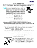
Page 10: ...led by a qualified electrician 2 8 CONDENSATE DRAIN The condensate is discharge at the system pressure Drain line should be secured Never point the condensate drain line towards anybody The dryer comes already fitted with two electronically level controlled BEKOMAT condensate drains Connect and properly fasten the condensate drain to a collecting plant or container The drain cannot be connected to...

Page 11: ...e system if installed Check the piping for air leakage Ensure the drain is regularly cycling wait for its first interventions 3 3 START UP AND SHUT DOWN Start up refer to paragraph 5 1 Control Panel Check the condenser for cleanliness Verify that the system is powered Switch on the dryer by closing the main switch on the control panel pos 1 Ensure that DMC14 electronic instrument is ON Wait a few ...

Page 12: ...680 115 1 60 210 2 3 240 2 7 70 66 30 scfm m 3 h l min F C F C F C F C psig barg psig barg psi bar NPT F oz kg cfm m 3 h model Btu h Ph V Hz W A W A dbA lbs kg AHT MODEL Air flow rate at nominal condition 1 Pressure DewPoint at nominal condition 1 Nominal max ambient temperature Min ambient temperature Nominal max inlet air temperature Nominal inlet air pressure Max inlet air pressure Air pressure...

Page 13: ... 0 19 8 0 22 1 6 2500 280 1 3 320 1 5 68 31 2 230 1 60 20 20 34 566 45 7 100 120 38 50 34 1 180 210 82 100 100 7 230 16 1 5 0 10 1 2 R134 a 7 0 20 500 290 1 10 FTP 008 1680 230 1 60 210 1 1 240 1 4 70 66 30 scfm m 3 h l min F C F C F C F C psig barg psig barg psi bar NPT F oz kg cfm m 3 h model Btu h Ph V Hz W A W A dbA lbs kg AHT MODEL Air flow rate at nominal condition 1 Pressure DewPoint at nom...

Page 14: ...ure is reduced to approximately 41 F 5 C causing additional water vapor to condense to liquid The liquid is continuously coalesced and collected in the dryer separator for automatic removal by the second condensate drain The cool moisture free compressed air then passes back through the air to air heat exchanger to be reheated to within the ambient temperature as it exits the dryer Refrigerant cir...

Page 15: ...flow direction 5 4 REFRIGERATING COMPRESSOR The refrigerating compressor is the pump in the system gas coming from the evaporator low pressure side is compressed up to the condensation pressure high pressure side The compressors utilized are manufactured by leading manufacturers and are designed for applications where high compression ratios and wide temperature changes are present The hermeticall...

Page 16: ...UNIT FREE FROM DUST AND OTHER IMPURITIES taken in by the fan 5 8 PRE FILTER FTP Series 3 micron Positioned at the outlet of the aftercooler it assures a good air cleanliness level in addition to the complete removal of the water condensed in the aftercooler REPLACE THE FILTERING ELEMENT CARTRIDGE AT LEAST EVERY 12 MONTHS 5 9 CAPILLARY TUBE It consists of a piece of reduced cross section copper tub...

Page 17: ... controller device on the pushing side carter of the compressor is enabled only if the pressure drops below the pre set value The values are automatically reset when the nominal conditions are restored Calibrated pressure R 404 A Stop 14 5 psig Restart 72 5 psig R 404 A Stop 1 0 barg Restart 5 0 barg PA This high pressure controller device located on the pushing side on the compressor is activated...

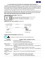
Page 18: ... see electric drawings into the attachments max 250V 1A min 5VDC 10mA with dryer off or in alarm conditions contact is open with dryer on and correct operating DewPoint contact is closed OPERATION After dryer starting the electronic controller displays current operating DewPoint it shows the measured temperature in Celsius degrees C with a 0 5 C resolution or in Fahrenheit degrees F with a 1 F res...

Page 19: ...nel here illustrated allows checking of drain working Power LED ON drain ready to work supplied Test test button discharge test keep pushed for 2 seconds MEMBRANE FUNCTION OF BEKOMAT 31 AHT 20 100 TROUBLESHOOTING BEKOMAT 31 AHT 20 100 The detection of defects should be carried out by qualified personnel SYMPTOM POSSIBLE CAUSE SUGGESTED ACTION No led lighting up Check for mains failure Verify the e...

Page 20: ...llation in other compressed air treatment units or the exchange against a different drain brand may lead to malfunction Do not exceed the max operating pressure see type plate MAKE SURE WHEN THE DRYER STARTS THE UPSTREAM VALVE IS OPEN CONTROL PANEL FOR BEKOMAT 32 AHT 150 350 The control panel here illustrated allows checking of drain working Power LED ON drain ready to work supplied Test test butt...

Page 21: ...re the drain is closed open it The dryer is not under pressure restore nominal condition Solenoid valve defective Replace Service Unit see para 5 17 MAINTENANCE BEKOMAT The internal printed circuit board is damaged replace the drain Condensate discharge only when Test button is pressed Too much internal dirt Replace Service Unit see para 5 17 MAINTENANCE BEKOMAT Drain keeps blowing off air Replace...

Page 22: ...TION Before maintenance or repair make sure the BEKOMAT is not pressurised ATTENTION Before installation maintenance or repair make sure the BEKOMAT is in a powerless state Before work disconnect from power supply MAINTENANCE BEKOMAT Remove Control Unit 1 by pressing the snap fit 2 Disconnect BEKOMAT from the condensate discharge 3 Disconnect Service Unit 4 from condensate inlet Check if new Servi...

Page 23: ...sate drain systems Verify the condenser aftercooler for cleanliness EVERY 200 HOURS OR MONTHLY With an air jet max 2 bar 30 psig blowing from inside towards outside clean the condenser aftercooler repeat this operation blowing in the opposite way be careful not to damage the aluminium fins of the cooling package At the end check the operation of the machine EVERY 1000 HOURS OR YEARLY Verify for ti...

Page 24: ... The safety thermo switch TS has been activated see specific point If the compressor still doesn t work replace it The fan of the condenser doesn t work Verify the electric wiring PV pressure switch is faulty replace it There is a leak in the refrigerating fluid circuit contact a refrigeration engineer If the fan still doesn t work replace it AHT 75 350 The Aftercooler fan doesn t work Verify the ...

Page 25: ...e room aeration is insufficient provide proper ventilation 2 The condenser is dirty clean it 3 The condenser fan doesn t work see specific point Reset the pressure switch pressing the button on the controller itself verify the dryer for correct operation The PA pressure switch is faulty contact a refrigeration engineer to replace it Where installed The PB low pressure switch has been activated The...

Page 26: ...CF3 1000 ppm 1300 R404A HFC CH2FCF3 C2HF5 C2H3F3 1000 ppm 3784 6 4 DISMANTLING OF THE DRYER If the dryer is to be dismantled it has to be split into homogeneous groups of materials Part Material Refrigerant fluid R404A R134a Oil Canopy and Supports Carbon steel Epoxy paint Refrigerating compressor Steel Copper Aluminium Oil Alu Dry Module Aluminium Condenser Unit Aluminium Copper Carbon steel Pipe...

Page 27: ...nger 26 Aftercooler 1 1 Insulation Material 27 Aftercooler fan 2 Refrigerant pressure switch PB Motor 3 TS safety thermo switch Blade 4 Refrigerant pressure switch PA Grid 5 Refrigerant pressure switch fan PV 28 Pre Filter 6 Refrigerating compressor 7 Hot gas by pass valve 51 Front panel 8 Condenser Air Cooled 52 Back panel 9 Condenser fan 53 Right lateral panel 9 1 Motor 54 Left lateral panel 9 2...

Page 28: ...ble of components IG Main switch K Refrigerating compressor KT Compressor thermal protection KR Compressor starting relay if installed CS Compressor starting capacitor if installed CR Compressor run capacitor if installed V Condenser fan CV Fan starting capacitor if installed DMC14 DMC14 Electronic Instrument Air Dryer Controller PR Temperature probe DewPoint PV Pressure switch Fan control PA Pres...

Page 29: ...7 1 1 AHT 20 50 AC 7 1 2 AHT 75 AC 7 1 3 AHT 100 150 AC ...

Page 30: ...7 1 4 AHT 200 250 AC 7 1 5 AHT 300 350 AC ...

Page 31: ...7 2 1 AHT 20 50 ...

Page 32: ...7 2 2 AHT 75 ...

Page 33: ...7 2 3 AHT 100 ...

Page 34: ...7 2 4 AHT 150 ...

Page 35: ...7 2 5 AHT 200 250 ...

Page 36: ...7 2 6 AHT 300 350 ...

Page 37: ...3 min 5VDC 10mA 8 9 T1 11 12 M KR CR M A P C KT CS Bn Air Dryer Controller Bn SEL0050 max 250V 1A 7 3 2 AHT 20 50 2 230 1 60 DEW POINT ALARM POWER 2 2 4 5 3 3 min 5VDC 10mA 8 9 T1 11 12 M KR CR M A P C KT CS Bn Air Dryer Controller Bn SEL0057 max 250V 1A 2 3 1 ...

Page 38: ... T1 11 12 M KR CR M A P C KT CS Bn Air Dryer Controller Bn Bn M SEL0051 min 5VDC 10mA max 250V 1A 7 3 4 AHT 75 100 2 230 1 60 DEW POINT ALARM POWER 2 2 4 5 3 3 8 9 T1 11 12 M KR CR M A P C KT CS Bn Air Dryer Controller Bn Bn M SEL0058 min 5VDC 10mA max 250V 1A 2 3 1 ...

Page 39: ...1 11 12 M M C KT CS Bn Air Dryer Controller Bn C S R M Bn CVA SEL0052 min 5VDC 10mA max 250V 1A 7 3 6 AHT 150 250 2 230 1 60 DEW POINT ALARM POWER 2 2 4 5 3 3 CVC 8 9 T1 11 12 M M C KT CS Bn Air Dryer Controller Bn C S R M Bn CVA SEL0059 min 5VDC 10mA max 250V 1A 2 3 1 ...

Page 40: ...7 3 7 AHT 300 350 2 230 1 60 Air Dryer Controller 3 3 2 4 5 11 12 2 POWER M CVC Bn Bn 3 2 1 9 DEW POINT ALARM T1 8 KT R CS S M C C M Bn CVA SEL0053 min 5VDC 10mA max 250V 1A ...

Page 41: ...NOTE ...

Page 42: ...NOTE ...

Page 43: ...NOTE ...

Page 44: ...GRAMAGLIA GO ...

Reviews: