background image


- 4 - 

  Chapter 1 Getting Started 

 
General Information 

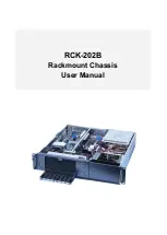
The RCK-202B Rackmount chassis supports full-size SBC through 2U PICMG1.0/ 1.3 

butterfly backplanes, and (2) 5.25" external drives bays, or (3) 3.5

” internal drive bays. The 

chassis has (2) 80mm replaceable high-speed ball-bearing fans, and supports PS2 or 

Mini-redundant power supply. 


Product Specification


Construction 

Heavy-duty steel with Ni plating 

Drive bay 

(2) 5.25" external drives bays, or (3) internal drive bays 

Cooling fan 

(2) 80mm replaceable high-speed ball-bearing fans 

Front Panel 

On/Off switch and Reset switch, 

(2) USB 2.0 ports, and PS/2 connector


Indicator 

Power On/Off and HDD activity LEDs 

Expansion 

5 x full-height expansion slots   

PICMG 1.0 / 1.3 backplane with PCI or PCIe slot expansion   

(refer to Appendix B) 

Dimension (W x D x H) 

434 x 450 x 88 mm; 17 x 17.7 x 3.5 inches 

Weight 

NW: 7.6kg / GW: 11.3kg 
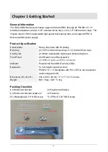
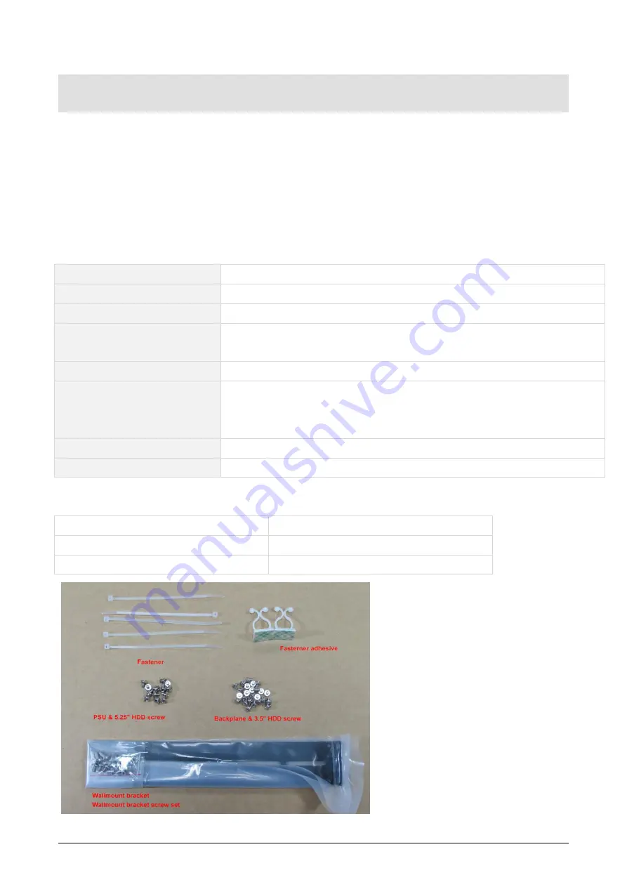
 

Packing Checklist 

2 x Wallmount bracket 

2 x Fasterner adhesive


8 x Wallmount bracket screw set 

4 x Fastener 

25 x Backplane & 3.5" HDD screw 

13 x PSU & 5.25" HDD screw


Summary of Contents for RCK-202B

Page 1: ...RCK 202B Rackmount Chassis User Manual...

Page 2: ...roduced copied or translated without prior notice to AICSYS Inc RCK 202B is trademark of AICSYS Inc Disclaimer Specification and information contained in this manual are provided for reference only We...

Page 3: ...Tools 5 Recommended Working Environment 5 Chassis Mechanical Drawing 5 Chapter 2 Installation Guide 6 Unpacking the Chassis 6 Removing the top cover 6 Installing the Power Supply Unit 7 Installing th...

Page 4: ...5 25 external drives bays or 3 internal drive bays Cooling fan 2 80mm replaceable high speed ball bearing fans Front Panel On Off switch and Reset switch 2 USB 2 0 ports and PS 2 connector Indicator...

Page 5: ...ver Flat Head Screwdriver Forceps for pulling out jumpers and screws Recommended Working Environment A flat anti static work surface is required when assembling a complete system Chassis Mechanical Dr...

Page 6: ...e present Make sure the chassis has not been damaged in anyway The installation steps outlined above are described in detail below Please refer to the relevant section s Removing the top cover The top...

Page 7: ...The RCK 202B chassis supports two 5 25 external drives bays or three 3 5 internal drive bays To install the drives please follow the steps outlined in the sections below 1 Remove the six screws and pu...

Page 8: ...to secure the backplane to the bracket Different backplane may have different Screw hole positions please refer to their own User manual for details Compatible backplane models are available in Appen...

Page 9: ...Unit Compatible Power Supply Units are listed in the table below Model number Wattage Type Dimension W x H x L SS 400ES 400W Single output 150 x 140 x 86mm SS 600ES 600W Single output 150 x 140 x 86mm...

Page 10: ...10 The Global Choice for Premium Industrial Computer Products www aicsys com...

Reviews: