
- 7 -
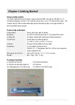
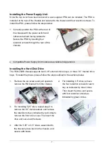
Installing the Power Supply Unit
Once the top cover have been removed, a user supplied PSU can be installed. The PSU is
installed at the rear of the chassis and secured to the chassis with four retention screws. To
install the PSU, please follow the steps below:
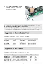
1. Correctly position the PSU at the rear of
the chassis with the power switch and
cable socket both facing outwards.
Secure the PSU by inserting four
retention screws through the rear of the
chassis
Compatible Power Supply Unit models are available in Appendix A.
Installing the Hard Disk Drive
The RCK-202B chassis supports two 5.25" external drives bays, or three 3.5
” internal drive
bays. To install the drives, please follow the steps outlined in the sections below.
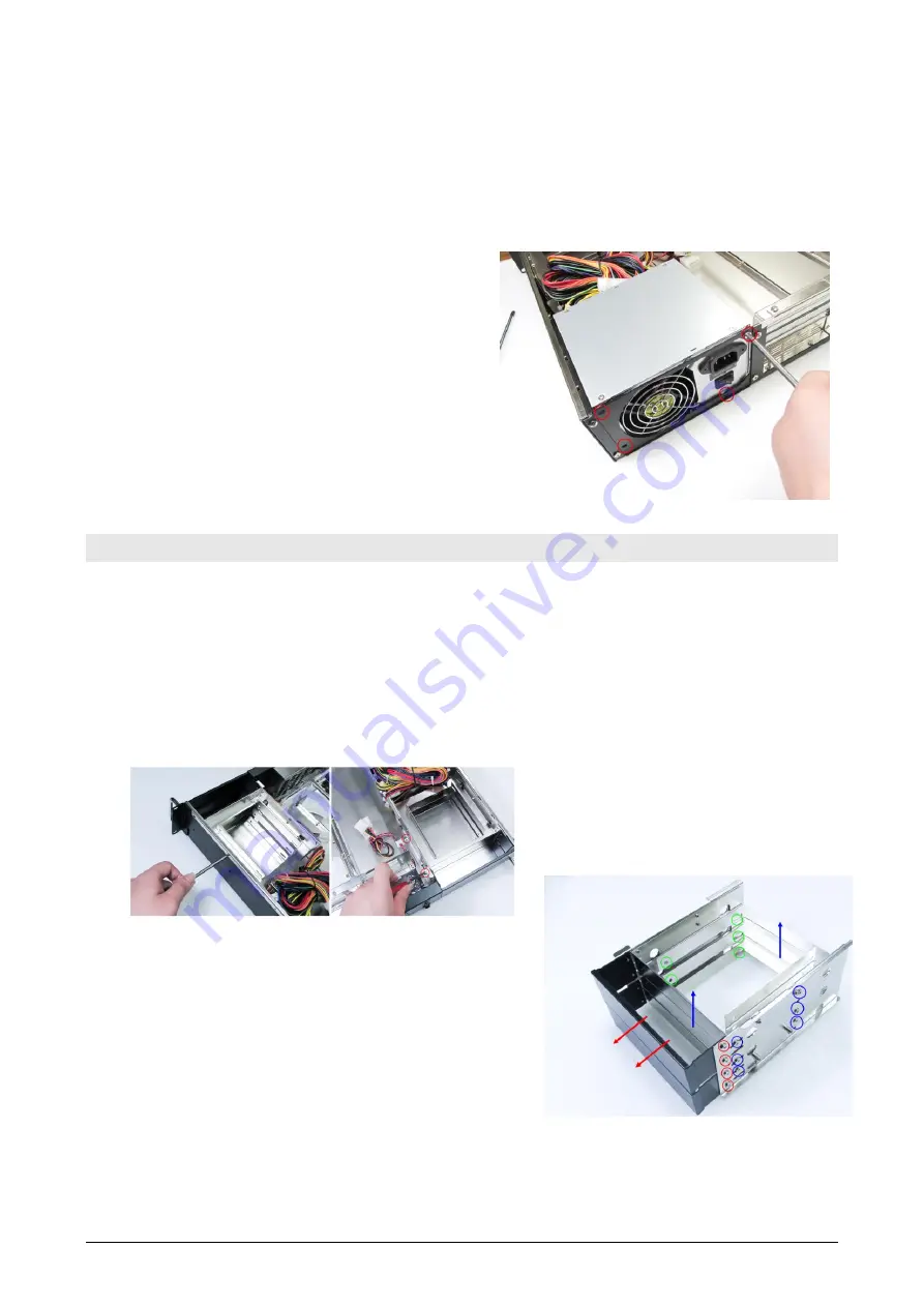
1. Remove the six screws and pull upside to
remove the HD bracket from the chassis
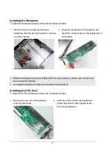
3. For installing 5.25
” drive, repeat step.2 to
remove the
3.5” drive brackets and remove
the retention screw (indicated by red circle) to
remove the front drive cover. The insert the
drive and secure with screws.
4. After the 5.25
” or 3.5” drives assembled to
the bracket, place back to the chassis, and
secure with crews.
2.
For installing 3.5” drive, remove
the four retention screws for each
bay as indicated by blue circles.
Then insert the drive and secure
with four retention screws as
indicated by green circles


