background image

- 9 - 

  Please make sure to disconnect the Power Supply before installing the CPU Card. 

  Do not turn on power during the CPU card installation 

  Electrostatic Discharge (ESD) can damage electronic components. To prevent damage 

to your system, use a grounded wrist strap designed to prevent static discharge 


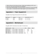
  Appendix A    Power Supply Unit 


Compatible Power Supply Units are listed in the table below: 


Model number 

Wattage 

Type 

Dimension (W x H x L) 

SS-400ES 

400W 

Single output 

150 x 140 x 86mm


SS-600ES 

600W 

Single output 

150 x 140 x 86mm


  Appendix B    Motherboard 


Compatible AICSYS motherboards are listed in the table below: 


Model number 

  Type 

PCI 

PCIe 

ISA 

BP-0602P-2U 

Full-size PICMG 1.0 Backplanes  2 

N/A 

BP-0604P-2U 

Full-size PICMG 1.0 Backplanes  4 

N/A 

N/A 

BPE-0502P-2U 

Full-size PICMG 1.3 Backplanes  2 

N/A 

BPE-0605E-2U 

Full-size PICMG 1.3 Backplanes  N/A 

N/A 


Summary of Contents for RCK-203BE

Page 1: ...RCK 203BE Rackmount Chassis User Manual...

Page 2: ...oduced copied or translated without prior notice to AICSYS Inc RCK 203BE is trademark of AICSYS Inc Disclaimer Specification and information contained in this manual are provided for reference only We...

Page 3: ...Tools 5 Recommended Working Environment 5 Chassis Mechanical Drawing 5 Chapter 2 Installation Guide 6 Unpacking the Chassis 6 Removing the top cover 6 Installing the Power Supply Unit 7 Installing the...

Page 4: ...1 3 5 internal drive Cooling fan 2 80mm high speed ball bearing fans Switch On Off switch and Reset switch Indicator Power On Off HDD activity LEDs I O 2 USB and 1 PS 2 Expansion 5 x full height expan...

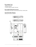
Page 5: ...ver Flat Head Screwdriver Forceps for pulling out jumpers and screws Recommended Working Environment A flat anti static work surface is required when assembling a complete system Chassis Mechanical Dr...

Page 6: ...bove are present Make sure the chassis has not been damaged in anyway The installation steps outlined above are described in details below Please refer to the relevant section s Removing the top cover...

Page 7: ...lling the Hard Disk Drive The RCK 203BE chassis supports one 5 25 and one 3 5 external drives bays To install the drives please follow the steps outlined in the sections below 1 Remove the four screws...

Page 8: ...backplane may have different Screw hole positions please refer to their own User manual for details Compatible backplane models are available in Appendix B Installing the CPU Card To install the CPU...

Page 9: ...Compatible Power Supply Units are listed in the table below Model number Wattage Type Dimension W x H x L SS 400ES 400W Single output 150 x 140 x 86mm SS 600ES 600W Single output 150 x 140 x 86mm App...

Page 10: ...10 The Global Choice for Premium Industrial Computer Products www aicsys com...

Reviews: