background image


- 6 - 

  Chapter 2 Installation Guide 


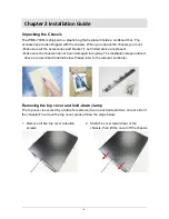
Unpacking the Chassis 

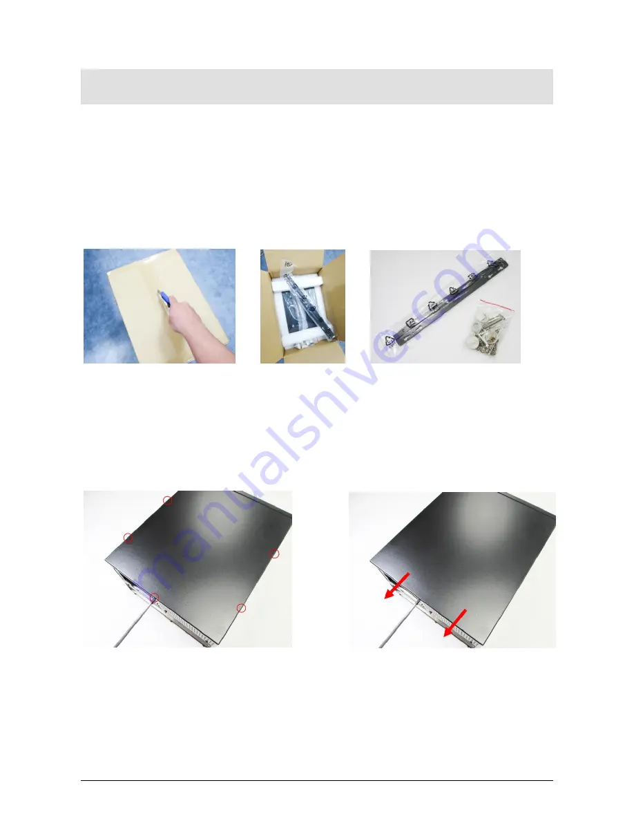
The WMC-704M is shipped in a plastic bag that is placed inside a cardboard box. The 

accessories are also shipped with the chassis. When you unpack the chassis you must: 

- Make sure all the accessories and bracket (1 set) listed above are present. 

- Make sure the chassis has not been damaged in anyway. The installation steps outlined 

above are described in detail below. Please refer to the relevant section(s). 


Removing the top cover and hold-down clamp 

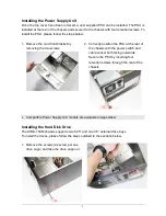
The top cover is secured by a total of six screws (two on each side and two on rear side of 

the chassis).To remove the top cover, please follow the steps below: 


1.  Remove all five top cover retention 

screws 

2.  Slide the cover toward rear of the 

chassis, then lift the cover off the chassis 


Summary of Contents for WMC-704M

Page 1: ...WMC 704M Wallmount Chassis User Manual...

Page 2: ...roduced copied or translated without prior notice to AICSYS Inc WMC 704M is trademark of AICSYS Inc Disclaimer Specification and information contained in this manual are provided for reference only We...

Page 3: ...Tools 5 Recommended Working Environment 5 Chassis Mechanical Drawing 5 Chapter 2 Installation Guide 6 Unpacking the Chassis 6 Removing the top cover and hold down clamp 6 Installing the Power Supply...

Page 4: ...ng fan 1 x 12cm ball bearing fan Switch On Off switch and reset switch Indicator Power On Off and HDD activity LEDs Expansion 7 x full height expansion slots Dimension W x D x H 330 x 406 x 204 2mm 13...

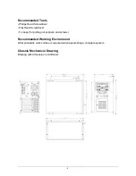
Page 5: ...ver Flat Head Screwdriver Forceps for pulling out jumpers and screws Recommended Working Environment A flat anti static work surface is required when assembling a complete system Chassis Mechanical Dr...

Page 6: ...ent Make sure the chassis has not been damaged in anyway The installation steps outlined above are described in detail below Please refer to the relevant section s Removing the top cover and hold down...

Page 7: ...2 Correctly position the PSU at the rear of the chassis with the power switch and cable socket both facing outwards Secure the PSU by inserting four retention screws through the rear of the chassis C...

Page 8: ...e 3 Carefully insert the ODD drive into the drive tray and secure the drive by inserting four retention screws four on each side through the sides of the drive tray 4 Carefully insert the 3 5 HDD into...

Page 9: ...board may have different Screw hole positions please refer to their own User manual for details Compatible motherboard models are available in Appendix B Installing the Expansion Card To install the E...

Page 10: ...x 140 x 86mm SS 400R8P 400W Redundant PSU 150 x 199 x 86mm R4S 400G1V2 400W Redundant PSU 150 x 174 x 86 mm R4S 500G1V2 500W Redundant PSU 150 x 174 x 86 mm R4B 500G1V2 500W Redundant PSU 150 x 199 x...

Page 11: ...11 The Global Choice for Premium Industrial Computer Products www aicsys com...

Reviews: