background image

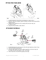
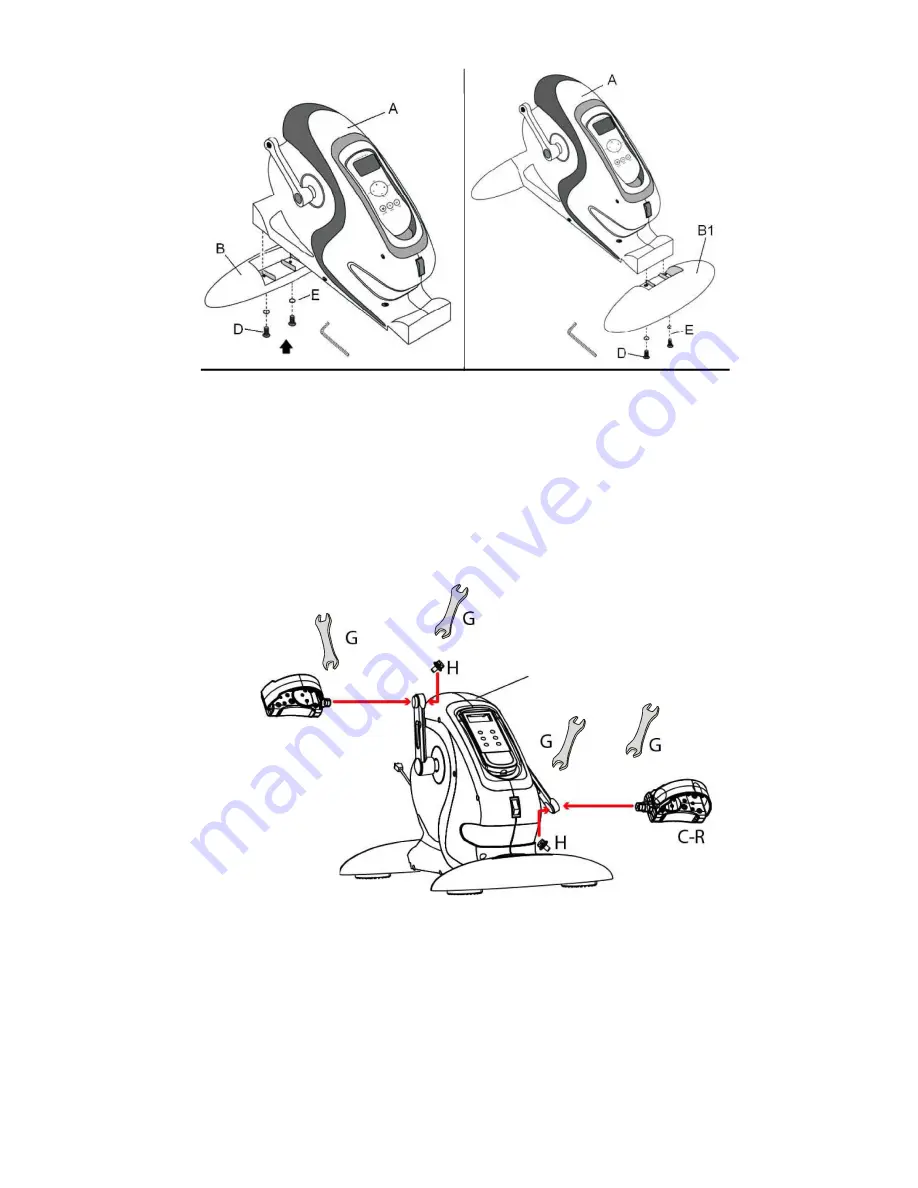
Fig.2 

Fig.3 

1.

Install the stabiliser bar (B) with the main body (A) as shown in Fig. 2.

2.

Keep  the screw  (D) and grower washer  (E)  firmly and drive them slowly with the 


hexagonal key (F).

3. Install

 the rear stabiliser bar  (B 1) marked with the main body  (A) 

as shown in Fig. 3.

4.

Apply the same procedure as step 2 above.  

C-L

Fig. 4 

1.

Install the left pedal (C-L) and one screw (H) on the main body (A) as shown in Fig 4.

2.

Screw well using the pe

d

als key (G)

3.

Install  the  right  pedal  (C-R)  and  the  other  screw  (H)  on  the  main  body  (A) 

according to the same procedures as step 1 and 2 above.

4.

Check the pedals are secure before applying any weight  

Usage and Maintenance Instructions 

Ver.12/201

6 (2532) 

FITTING THE STABILISERS

ATTACHING THE PEDALS

4

Summary of Contents for VP159R

Page 1: ...EN Electric Mini Exercise Bike VP159R Usage and Maintenance Instructions...

Page 2: ...he 0 position and then unplug 8 To unplug the machine from the wall socket 9 Please consult a medical professional before undertaking a new form of exercise or using new exercise equipment 10 As with...

Page 3: ...ay with the appliance 16 Cleaning and user maintenance shall not be made by children without supervision 17 Do not place the mains lead beneath a carpet or rug 18 Ensure that the cable does not come i...

Page 4: ...3 4 Apply the same procedure as step 2 above A C L Fig 4 1 Install the left pedal C L and one screw H on the main body A as shown in Fig 4 2 Screw well using the pedals key G 3 Install the right pedal...

Page 5: ...machine on press 1 on the remote control 2 To switch the machine off press 1 on the remote control Switch the red button below the remote control support to position 0 and then unplug the unit from th...

Page 6: ...the session CLEANING Switch off and unplug the unit then clean using a non abrasive cleaner or mild detergent with a soft cloth Abrasive cleaners and or abrasive cleaning pads may seriously damage th...

Page 7: ...blue wire to the terminal labelled N Connect the green yellow to the terminal labelled with the earth symbol or E Make sure that the cord grip is positioned correctly over the outer sheath of the cab...

Page 8: ...any unnecessary risks when using this product as the user you must accept liability for safety when using the product Please do not hesitate to contact the person who issued this product to you or th...

Reviews: