background image

Doc


No.


FM5640


issue


3


Page


28


16.


IP

DECT


400


MULTI

CELL


SYSTEM


INSTALLATION


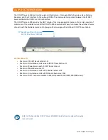
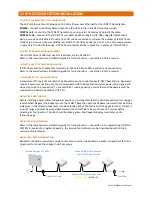
IP-DECT SERVER 400 (MULTI-CELL) PROGRAMMING


The


IP

DECT


Server


400


must


have


its


IP


address


set


to


192.168.0.3


and


its


Radio


Part


Number


set


to


3.


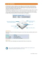
IP-DECT BASE STATION PROGRAMMING


IP

DECT


Base


Stations


must


have


their


IP


addresses


set


192.168.0.4/5/6


and


Radio


Part


Numbers


4/5/6.


Refer


to


the


manufacturers


installation


guide


for


full


instructions


see


section


6.


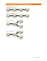
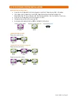
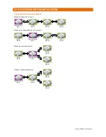
2 CHANNEL MULTI-CELL REPEATERS 


A


maximum


of


three


2


Channel


Multi

Cell


Repeaters


can


be


connected


to


the


IP

DECT


Server


400


Multi

Cell


plus


three


per


IP

DECT


Base


Station


(total


12


per


site).


Repeaters


require


a


power


connection


only;


they


communicate


with


the


Server/Base


Station


via


low


power


radio


signals


and


do


not


require


a


line


connection.


To


maintain


DECT


coverage


during


a


mains


failure


all


Repeaters


must


be


connected


to


a


battery


backed


12V


DC


PSU.


REPEATER POSITIONING


Before


installing


power


cables


to


Repeater


positions,


it


is


important


that


the


optimum


position


for


coverage


is


established.


Register


the


Repeater


onto


the


IP

DECT


Server/Base


then


with


the


Repeater


powered


from


a


battery


walk


away


in


the


direction


that


cover


is


to


be


extended.


When


the


red


LED


on


the


Repeater


starts


to


flash


it


is


out


of


range


and


must


be


moved


back


towards


the


Server/Base


by


a


minimum


of


5


metres


before


selecting


its


final


location.


The


LED


should


be


steady


green.


See


Repeater


Deployment


Rules


on


the


following


page.


REPEATER PROGRAMMING


Refer


to


the


manufacturers


installation


guide


for


full


instructions


see


section.


A


programming


kit


(P/No.


ZCS729)


is


required


to


program


Repeaters,


the


Service


Tool


software


can


be


downloaded


via


the


link


in


section


6


of


this


manual.


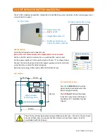
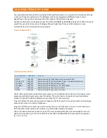
REPEATER POWER CONNECTION 


Repeaters


should


be


connected


using


8


core


cables;


cores


can


be


doubled

up


and/or


looped


back


to


form


a


ring


circuit


to


reduce


the


voltage


drop


if


necessary.


Typically,


the


maximum


distance


to


a


Repeater


should


not


exceed


100


metres.


Note:


connect


a


maximum


of


6


Repeaters


per


12V


2A


PSU.


Maximum


12


x


2


Channel


Multi

Cell


Repeaters


(3


on


Multi

Cell


Wireless


Server


+


3


per


DECT

IP


Base


Station)


240V


AC


Battery


Backed


12V


DC


PSU


Repeater


Power


Lead


Colour


Code


YELLOW


=


12V


BLACK


=


0V


Use


8


Core


Cable


Max


100m

Summary of Contents for Touchsafe Pro IP-DECT 400 Multi-Cell

Page 1: ...icy of continual product improvement and reserves the right to modify the specification of its products If any variation to the details in this document are suspected please contact Aidcall s Technica...

Page 2: ...m Installation 21 16 IP DECT 400 Multi Cell System Installation 27 17 IP DECT 6500 System Installation 31 18 Matrix Eternity PE IP PBX 35 19 Specification 7722 DECT Handset Charger 36 20 Specification...

Page 3: ...ations Repeaters will be determined by a site survey prior to commencing the installation All Base Stations are star wired from a central PoE Data Switch on Cat5e cable max length 100 metres Repeaters...

Page 4: ...on See section 7 of this manual for details of cable type recommended colour code and cable length restrictions DECT products should be located at least 5 metres away from any other electronic equipme...

Page 5: ...e to ensure the safe disposal and recycling of batteries Return used batteries to your supplier or drop off at your local municipal waste recycling depot NTENTS 4 MAINTENANCE CARE For peace of mind an...

Page 6: ...e corners if this is the case then additional Repeaters will be required Repeaters are generally placed in a star configuration around the Server Base station however it is possible to extend the cove...

Page 7: ...uct_finder_tabs 1 type All Spectralink 7722 42 Handset quick start guide Spectralink 7722 42 Handset user guide Spectralink Handset Management user guide Spectralink Handset Battery information guide...

Page 8: ...WIRING REQUIREMENTS IP DECT 400 SINGLE CELL SYSTEM ____________________________________________________________________________________ IP DECT 400 MULTI CELL SYSTEM _________________________________...

Page 9: ...must not exceed 100 metres Make all 8 connections WALL SOCKET FROM REAR DECT Repeaters should be connected to the 12V 2A Battery Backed PSU using 8 Core alarm cable Aidcall Part No YW1730 Connect a ma...

Page 10: ...st and intuitive to understand for healthcare professionals The Spectralink 7722 DECT handset comes complete with a desktop charger and a UK plug top power supply Aidcall bundle Part No ZXT526 ACCESSO...

Page 11: ...nd it is possible to expand the numbers should your needs grow With the Multi Charger you can benefit from access to fully charged handsets at any time it is easy to see which handsets are charged and...

Page 12: ...sure always check the Model No label on the rear of the unit to be sure of which product you are looking at the Multi Cell version has an additional licence applied during manufacture LED INDICATOR Th...

Page 13: ...have the same fixing centres FRONT REAR All DECT radio parts should be mounted vertically on the wall at least 2 4 metres above floor level but no higher than 6 metres They will normally be fitted wi...

Page 14: ...kes it easy to increase the number of voice channels with the Media Resource and or geographical coverage with additional IP DECT Base stations SYSTEM CAPACITY Max No of IP DECT Base Stations 512 Max...

Page 15: ...del No label on the rear of the unit to be sure of which product you are looking at LED INDICATOR The front cover Status LED will indicate the Repeater status by different colours and flash patterns s...

Page 16: ...te the mains plug is fitted with a 240V AC 5A BS1362 fuse PSU FIXING The PSU should only be opened during installation and service the lid must be screwed shut at all other times to prevent the risk o...

Page 17: ...ge voltage across the battery leads is between 13 6V DC and 14 2V DC 13 8V nominal If the battery shows any signs of damage swelling or leakage during an annual inspection it should be replaced immedi...

Page 18: ...backed output sockets Serial Port B is connected to the RS232 Pager Port on any Touchsafe Pro Nursecall panel using a 2 metre Cat5e STP Patch lead and a 9 pin D sub female RJ45 adapter RS 818 700 Note...

Page 19: ...This cable is available from Aidcall by the metre Part No YW1730 Configure the 9 Pin D Sub Female RJ45 Adapter using the colour code in the table below Plug the Patch Lead into 9 Pin D Sub Female RJ45...

Page 20: ...pattern to sound for each call type Select the Panel ID the Integrator is being connected to from the Paging Panel pull down box Note this only needs to be set on the Master Panel ID 1 Press the Save...

Page 21: ...ptional Integrator IP PBX must be powered from the battery backed output sockets on the UPS PoE INJECTOR CONNECTION The PoE injector provides Power over Ethernet for the IP DECT Server 400 Single Cell...

Page 22: ...ter onto the IP DECT Server 400 then with the Repeater powered from a battery walk away in the direction that cover is to be extended When the red LED on the Repeater starts to flash it is out of rang...

Page 23: ...P DECT 400 Single Cell Server RPN 3 A maximum of 3 Repeaters can be configured in a chain If you have up to 3 Repeaters they should be numbered 67 131 195 i e RPN 3 64 128 192 If you have more than 3...

Page 24: ...RPN 3 Single Cell Server RPN 3 Single Cell Server RPN 3 15 IP DECT 400 SINGLE CELL SYSTEM INSTALLATION 3 REPEATER DEPLOYMENT EXAMPLES CONTINUED 3 Repeaters connected directly Y shaped 3 Repeater depl...

Page 25: ...ater RPN 35 Repeater RPN 67 Repeater RPN 163 Repeater RPN 99 Repeater RPN 131 Repeater RPN 227 Single Cell Server RPN 3 Single Cell Server RPN 3 Single Cell Server RPN 3 Single Cell Server RPN 3 Singl...

Page 26: ...peater RPN 131 Repeater RPN 99 Repeater RPN 35 Repeater RPN 67 Repeater RPN 131 Repeater RPN 195 Single Cell Server RPN 3 Single Cell Server RPN 3 15 IP DECT 400 SINGLE CELL SYSTEM INSTALLATION 6 REPE...

Page 27: ...N To maintain DECT operation during a mains failure the Ethernet Switch and optional Integrator IP PBX must be powered from the battery backed output sockets on the UPS 16 PORT ETHERNET SWITCH CONNECT...

Page 28: ...coverage is established Register the Repeater onto the IP DECT Server Base then with the Repeater powered from a battery walk away in the direction that cover is to be extended When the red LED on the...

Page 29: ...ell Server they should be numbered 67 131 and 195 i e RPN 3 64 128 and 192 A maximum of 3 Repeaters can be configured on an IP DECT Base Station RPN 4 5 6 If you have up to 3 Repeaters on an IP DECT B...

Page 30: ...er RPN 64 Repeater RPN 128 Repeater RPN 192 Multi Cell Server Base RPN 3 6 Multi Cell Server Base RPN 3 6 Multi Cell Server Base RPN 3 6 Multi Cell Server Base RPN 3 6 16 IP DECT 400 MULTI CELL SYSTEM...

Page 31: ...2 DECT Handset inc Charger PSU Max 64 per site 4096 with additional licences ZXT548 700VA UPS 1 per site E40062 12V 2A Battery Backed PSU 1 per 6 Repeaters W03076 Integrator 1 per site optional W03220...

Page 32: ...l Multi Cell Repeaters can be connected per IP DECT Base Station Repeaters require a power connection only they communicate with the Base Station via low power radio signals and do not require a line...

Page 33: ...tation RPN IP Address If you have up to 3 Repeaters on an IP DECT Base Station they should be numbered as Base Station No X 64 128 and 192 The first Base Station is No 4 second No 5 and so on A maximu...

Page 34: ...PN 64 Repeater RPN 128 Repeater RPN 192 IP DECT Base Station RPN 4 IP DECT Base Station RPN 4 IP DECT Base Station RPN 4 IP DECT Base Station RPN 4 Repeater RPN 128 17 IP DECT 6500 SYSTEM INSTALLATION...

Page 35: ...s can be desk or wall mounted as standard optional PE 19RACK brackets are available for 19 rack mounting Plug in PE CO4 SLT4 cards allows up to 4 analogue trunks for access to the outside world and 4...

Page 36: ...t tight and water splash proof Dimensions 148 4mm x 50 4mm x 21 6mm HxWxD Weight 115 grams including battery Operating Temperature Range 0o C to 40o C Desktop Charger Manufacturer Model No Spectralink...

Page 37: ...EN55022 EN6100 3 2 EN61000 4 2 EN55024 Protection Electronic OVP OLP Short Circuit Protection LED Indicator Green Supply Healthy Input Voltage Current 100 240VAC 47 63Hz 1 0A Output Voltage Current 6V...

Page 38: ...rams Operating Temperature Range 10o C to 40o C Operating Humidity 20 80 RH Non condensing IP DECT Server 400 Multi Cell Manufacturer Model Spectralink 0234 4500 1407 5520 Multi cell Licence Aidcall P...

Page 39: ...96 EC Network Provisioning RJ45 10 100 Mbps Ethernet Port DHCP NTP Protocol Support SIP Session Initiated Protocol System Architecture 64 users 32 simultaneous calls Optional Licences 150 500 1500 40...

Page 40: ...ernet Port DHCP NTP LED Status indication Max No of Speech Channels 12 Typical Range 20 50 metres indoor 300 metres outdoor Peak Transmit Power 250mW Typical Receiver Sensitivity 90dBm Electrical Requ...

Page 41: ...ons 100mm x 100mm x 30mm HxWxD Weight 113 grams Operating Temperature Range 10o C to 40o C Operating Humidity 20 80 RH Non condensing 4 Channel Multi Cell Repeater Manufacturer Model No Spectralink 02...

Page 42: ...mperature Range 0o C to 70o C Operating Humidity 45 55 RH Non condensing Integrator Power Supply Supplier Model No RS Components 765 3311 EMC Approvals EN55022 2006 EN61000 3 2 2006 Safety Approvals U...

Page 43: ...76mm x 36mm WxHxD Weight 138 grams Operating Temperature Range 0o C to 60o C Operating Humidity 10 90 RH Non condensing 5 Port Ethernet Switch Manufacturer Model No Netgear ProSAFE FS105 Aidcall Part...

Page 44: ...nly Dimensions 287mm x 103mm x 27mm WxDxH Weight 810 grams Operating Temperature Range 0o C to 40o C Operating Humidity 10 90 RH Non condensing 24 Port Ethernet Switch 24 PoE Manufacturer Model No Net...

Page 45: ...A 20mm Glass Battery Protection Re settable PTC Enclosure Material White powder coated 18 SWG steel with hinged lid Ingress Protection Rating IP41 indoor sheltered Dimensions 200mm x 230mm x 80mm HxWx...

Page 46: ...ge on utility 230V AC 47 63Hz Output Voltage on battery 230V AC 8 50Hz 1Hz Output Connections 8 x BS 1363 Sockets 4 with battery back up plus surge protection and 4 with surge protection only Battery...

Page 47: ...oprietary Digital Key Phones or DSS Consoles 16 TWT Ports To connect Two Wires Trunk lines 12 BRI Ports To connect ISDN BRI Network or ISDN compatible devices 6 T1 E1 PRI Ports To connect T1 or E1 or...

Reviews: