background image

Summary of Contents for MX180T

Page 1: ...MX180T MX180TP Triple Output Multi Range DC Power Supply INSTRUCTION MANUAL ...

Page 2: ...Settings Limits 11 7 2 Setting with Individual Output Screens 11 7 3 Power Display VxA 12 7 4 Selecting Current Meter Averaging 12 7 5 Setting Over Voltage and Over Current protection 12 7 6 Setting the Voltage Current Range 13 7 7 Selecting Voltage Tracking 13 7 8 Store and Recall of Settings 13 7 9 The System Menu Screen 14 7 10 Locking the Front Panel 14 8 Display Symbols 15 9 Menu Advanced Fun...

Page 3: ...nterface 24 12 2 3 USB Interface and Device Driver Installation 25 12 2 4 LAN Interface 25 12 2 5 LAN IP Address and Hostname 26 12 2 6 Interface Locking 27 12 2 7 Status Reporting 28 13 Remote Commands MX180TP only 33 13 1 General 33 13 1 1 Remote and Local Operation 33 13 1 2 Remote Command Handling 33 13 1 3 Remote Command Formats 33 13 1 4 Command Timing 34 13 1 5 Response Formats 34 13 2 Comm...

Page 4: ...jump back to continue reading the original section N B for hyperlink navigation within Acrobat Reader enable show all page navigation tools or use the keyboard shortcuts Alt Left Arrow and Alt Right Arrow The Table of Contents is also fully hyperlinked and is replicated within the Bookmarks pane Note The latest revisions of this manual device drivers and software tools can be downloaded from http ...

Page 5: ...inear final regulation to give good noise and transient performance All information is displayed on a large backlit graphic LCD and control is via soft keys together with a numeric keypad and spin wheel Advanced features include 50 settings memories for each output plus 50 further memories that record the settings for all three outputs together Multi On and Multi Off keys supplement the individual...

Page 6: ...tension cord without a protective conductor When the instrument is connected to its supply terminals may be live and opening the covers or removal of parts except those to which access can be gained by hand is likely to expose live parts The apparatus shall be disconnected from all voltage sources before it is opened for any adjustment replacement maintenance or repair Capacitors inside the power ...

Page 7: ...r outside the instrument will make the instrument dangerous Intentional interruption is prohibited 3 3 Mounting This instrument is suitable both for bench use and rack mounting It is delivered with feet for bench mounting The front feet include a tilt mechanism for optimal panel angle A rack kit for mounting in a 19 rack is available from the manufacturers or their agents and distributors overseas...

Page 8: ...minal and earth ground is 300VDC the maximum permissible voltage between either terminal of one output and either terminal of another output on the same power supply is also 300VDC WARNING Such voltages are exceedingly hazardous and great care should be taken by the user The front terminals are intrinsically touch proof but hazard may still exist depending upon the type of connection made to the t...

Page 9: ...e key turns the output on or off The on state is indicated by the key being illuminated in red At power up the default behaviour is for all the outputs to be set to off However the user can change this default setting such that the outputs are restored to their condition when the instrument was switched off This change is made from System Preferences see section 10 1 Multi On Multi Off It is also ...

Page 10: ...oltage CC constant current or SET Settings SET is displayed when the output is off The two meters directly below show the set values for voltage and current when the output is off and the voltage and current being supplied to the load when the output is on With an output on the three lines below the meters show the set voltage Vset the set current Iset and the output range Range If the output is o...

Page 11: ... 0 01 volts when the 120V 3A range is selected 6 4 Setting with the Spin Wheel Vset Iset Voltage or current can alternatively be set using the spin wheel The wheel is disabled by default but can be enabled by pressing the key below it which toggles its action on or off When enabled the key is illuminated The wheel changes the output settings immediately no OK confirmation is required The wheel has...

Page 12: ...laced next to it It is also possible to set an audible alert see section 10 2 Output Off When an output is off the meters show these set values and SET is shown on the top line of the display When an output is on the values of voltage generated and current flowing are shown together with CV or CC View Settings View Limits It is also possible to view the set values for all three outputs at any time...

Page 13: ...oltage protection OVP and over current protection OCP If a voltage is detected that exceeds the OVP level or a current is detected that exceeds the OCP level the output is switched off and the message OVP or OCP is displayed OVP is adjustable between 1V and 140V for output 1 1V and 70V for output 2 and 1V and 14V for output 3 OCP is adjustable between 0 01A and 22A for output 1 0 01A and 12A for o...

Page 14: ...can be changed If after 5 seconds this condition has not been met a warning screen is displayed From this screen it is possible to retry change the range cancel the request or set defaults and restart the instrument 7 7 Selecting Voltage Tracking By default all outputs are completely independent However it is possible to make the voltage of output 2 always equal to the voltage set on output 1 This...

Page 15: ...te confirmation screen it is also possible to delete the contents of all 50 locations by pressing Del All A confirmation is required Store and Recall for Multiple Outputs It is also possible to store and recall settings for all three outputs simultaneously This is described in Advanced Functions section 9 3 7 9 The System Menu Screen The operation of the System Menu screen is selected with the key...

Page 16: ...ly 120V range Flashing lightning symbol after voltage value Flashing lightning symbol after voltage value Multi On Multi Off not set to defaults set to Delayed or Never Clock symbol on top line next to the mode indication for the affected output Clock symbol on top line Power supply under remote control MX180TP only REM shown at top right hand side REM shown at top right hand side LAN connection s...

Page 17: ...g Menu Voltage Tracking Setup By default all outputs are completely independent However it is possible to make the voltage of output 2 always equal to the voltage set on output 1 This is called voltage tracking Tracking voltages can be useful in setting up adjustable voltages of equal or opposite polarity or when outputs are wired in parallel or in series Voltage tracking can alternatively be set ...

Page 18: ...fail to complete if it invokes certain range changes see section 7 6 for more information Current meter averaging being set on is indicated by the symbol after the set current value Multi On Multi Off settings other than both set to Quick are indicated by a clock symbol after the On Off state Note that output delay settings are only applied when the Multi On Multi Off function is used and not when...

Page 19: ... long delays is in progress a second press of the Multi Off key will turn all three outputs off immediately including any outputs omitted from the sequence i e set to Never Thus a double press or press and hold of the Multi Off key will immediately turn off all the outputs regardless of the sequence settings The individual output On Off keys also remain active during a sequence and can be used to ...

Page 20: ...LCD Contrast Menu Adjust LCD Contrast The LCD contrast can be adjusted over a wide range The setting is displayed numerically as a percentage The display can also be inverted from black on white to white on black 9 9 Calibration Menu Calibration The Calibration function enables the instrument to be re calibrated when required Calibration will overwrite the existing settings and should only be carr...

Page 21: ...uch that the outputs are restored to their condition when the instrument was powered down The default behaviour also returns the settings set volts set current range etc to those that existed at power down This can be changed so that the settings are always at factory defaults see section 18 This includes all outputs being set to Off 10 2 Alert Sound Beep Set beep Disable beep An alert sounder is ...

Page 22: ...aintain stability and good transient response This capacitor charges to the output voltage and short circuiting of the output will produce a current pulse as the capacitor discharges which is independent of the current limit setting 11 3 Output On Off and Response Speed The output On Off control of the power supply is entirely electronic The Off condition is achieved by setting the voltage to zero...

Page 23: ... in a situation where damage to the device under test might otherwise occur 11 4 1 OCP Trip at Output On If the OCP level is set to a very low level whilst also being below the set current level it is possible for a trip condition to be created when the output is switched on This is caused by the current needed to charge the output capacitance Whether a trip occurs is a function of the OCP trip re...

Page 24: ...nals but never to both pairs of terminals at the same time Switch back to LOCAL when remote sensing is not in use Interface Connections Interface connectors for USB RS 232 LAN and GPIB are mounted on the rear panel These are described in detail within the following sections 12 2 Remote Interface Configuration The MX180TP model can be remotely controlled via its RS232 USB GPIB or LAN interfaces The...

Page 25: ...change the address use the spin wheel to set the desired address and then press the OK Exit soft key The interface will operate with any commercial GPIB interface card using the device drivers and support software provided by the manufacturer of that card 12 2 2 RS232 Interface The 9 way D type serial interface connector is located on the instrument rear panel It should be connected to a standard ...

Page 26: ...computer for driver software and then locate the INF file on the CD as described above Once Windows has installed the device driver it will assign a COM port number to this particular unit This number will depend on previous COM port assignments on this PC and it may be necessary to use Device Manager to discover it Each instrument has a unique USB identifier which is remembered by the system so i...

Page 27: ...nterfaces screen Menu Remote Control Interfaces Alternatively the address can be obtained from the DHCP server or by using the LXI Discovery Tool described below mDNS and DNS SD Support The instrument supports these multicast name resolution protocols which allow a meaningful host name to be assigned to the unit without needing an entry in the database of a central nameserver The desired hostname ...

Page 28: ...uld normally have a VISA resource name of TCPIP0 192 168 0 100 inst0 INSTR but for this instrument the name must be modified to read TCPIP0 192 168 0 100 9221 SOCKET where 9221 is the TCP port used by this instrument for control and monitoring see below XML Identification Document URL As required by the LXI standard the instrument provides an XML identification document that can be queried via a G...

Page 29: ...y contain is shown in the Status Model Diagram and described in detail below but in brief the status is maintained using five primary registers the Limit Event Status Register for each output the Standard Event Status Register and the Execution Error Register A summary is reported in the Status Byte Register as selected by four masking registers the Limit Status Enable Register for each output and...

Page 30: ...ror occurs because the controller has not issued commands and read response messages in the correct sequence Bit 0 Operation Complete Set in response to the OPC command The Standard Event Status Register is read and cleared by the ESR query which returns a decimal number corresponding to the contents On power up it is set to 128 to report the power on bit The Standard Event Status Enable Register ...

Page 31: ...bit will be cleared after the Response Message Terminator has been sent Bit 2 LIM3 The Output3 Limit Status Bit This will be set if any bits in the Limit Event Status register for output3 are set and corresponding bits are set in the Limit Event Status Enable register LSE3 Bit 1 LIM2 The Output2 Limit Status Bit This will be set if any bits in the Limit Event Status register for output2 are set an...

Page 32: ...f the response formatter is waiting to send a response message and a PROGRAM MESSAGE TERMINATOR has been read by the parser or the input queue contains more than one END message This will cause the Query Error bit to be set in the Standard Event Status Register a value of 1 to be placed in the Query Error Register and the response formatter to be reset discarding the waiting response message The p...

Page 33: ...Page 32 ESE ESE Standard Event Status Enable Register STB Status Byte Register SRE SRE Status Byte Enable Register PRE PRE Parallel Poll Response Enable Register Status Model ...

Page 34: ...or query is complete Responses are sent to the interface which issued the query There is no internal output queue so on the GPIB interface the response formatter will wait indefinitely if necessary until the complete response message has been read by the controller before the parser is allowed to start the next command in the input queue On all other interfaces the response message is immediately ...

Page 35: ...eyword followed by either text or a number in one of the following formats NR1 An integer without a decimal point or a unit NR2 A fixed point number with a fractional part but no exponent part NR3 A floating point number with both a fractional part and an exponent part CRD Character Response Data consisting of the text characters listed N The number of the output or status register to which the co...

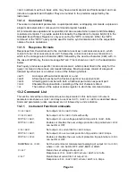
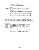
Page 36: ...ltage by step size with verify DECV N Decrement the output N voltage by step size DECV N V Decrement output N voltage by step size with verify INCI N Increment the output N current limit by step size DECI N Decrement the output N current limit by step size OP N NRF Set output N on off where NRF has the following meaning 0 OFF 1 ON OP N Returns output N on off status The response is NR1 RMT where 1...

Page 37: ...l of the firmware installed RST See Section footnote Resets the functional parameters of the instrument to the default settings as listed in the Factory Default Settings see section 18 Does not affect the contents of the Save and Recall stores Does not affect any remote interface settings SAV NRF Save the settings for all three outputs simultaneously to the store specified by NRF where NRF can be ...

Page 38: ...or Register The response format is NR1 RMT QER Query and clear Query Error Register The response format is NR1 RMT STB Report the value of the Status Byte The response is NR1 RMT Because there is no output queue MAV can only be read by a GPIB serial poll not by this query as any previous message must have already been sent SRE NRF Sets the Service Request Enable Register to NRF SRE Report the valu...

Page 39: ...s will be sought The response is CRD RMT where CRD is DHCP AUTO or STATIC The following commands specify the parameters to be used by the LAN interface Note a power cycle is required after these commands are sent before the new settings are used or returned in response to the queries listed above The instrument does not attempt to check the validity of the IP address or netmask in any way other th...

Page 40: ...C supply Remove the 2 cover securing screws at the rear and slide back and lift off the cover Replace the fuse with one of the correct type and refit the cover Note that the main function of the fuse is to make the instrument safe and limit damage in the event of failure of one of the switching devices If a fuse fails it is therefore very likely that the replacement will also blow because the supp...

Page 41: ...ually settable delay between pressing of the Multi On or Multi Off key and the turning on or off of the respective output Delays settable between 10ms and 20 seconds Separate delays for On and Off can be set Outputs can also be omitted from Multi On or Multi Off control Output Terminals Universal 4mm safety binding posts on 19mm 0 75 spacing for Output screwless terminals for Sense MX180TP also ha...

Page 42: ...utput with High Medium or Low settings V x A O P 1 and O P 2 Resolution 0 001W to 100W 0 01W above 100W O P3 Resolution 0 01W Accuracy 0 5 of reading 3 digits SETTING MEMORY STORES Stores for Individual Outputs 50 store positions for each output Values stored are Range Voltage Current OVP and OCP Stores for All Outputs 50 store positions operating on all three outputs simultaneously Values stored ...

Page 43: ...ng Range 5ºC to 40ºC 20 to 80 RH Storage Range 40ºC to 70ºC Environmental Indoor use at altitudes up to 2000m Pollution Degree 2 Safety EMC Complies with EN61010 1 EN61326 1 For details request the EU Declaration of Conformity for this instrument via http www aimtti com support serial no needed Size 210 x 130 x 375mm WxHxD half rack width x 3U height Weight 5 8kg Options 19 inch rack kit for one o...

Page 44: ......

Reviews: