4
3
–
Installation, connections and powering
Each item of the kit needs to be carefully installed, MyChron5 660 first. Incorrect installation may result in system malfunction.
3.1
–
Installing MyChron5 660
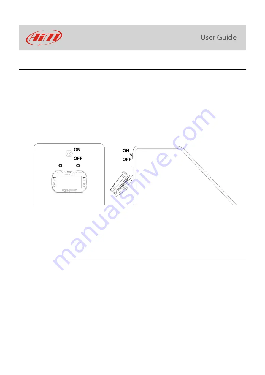
MyChron5 660 allows the mechanics to set up the engine carburetion immediately before the race. For this reason it is
important to install it in a place where the mechanics can see its display while working on the dragster engine. A commonly used
position is the metal bulkhead which separates the racer
’s seat f
rom the engine. AiM recommends to install MyChron5 660
under the engine ON/OFF switch.
As shown here above on the right the logger needs a bracket. Use an aluminium or steel self-made bracket a 0.1
”
(2.5 mm)
thickness so to resist the vibration when the engine is on. Firmly fix the bracket to the vertical bulkhead and then fix MyChro5
660 to the bracket. Please be careful not to overtighten the mounting nut; this can cause damage to the display unit case.
3.2
–
Installing the RPM wire
RPM wire needs to be connected to the dragster ON/OFF switch. The switch is in most cases a 2 poles (some switches only are a
1 pole). The two poles are RPM and coil. RPM wire should be going to the coil side of the kill switch. Running it to the grounded
side of the switch causes RPM signal to drop in and out and sometimes not to work at all. Being the ON/OFF switch opposite of
the bulkhead drill a 0.2
”
(5mm) hole inside the bulkhead and remember to insert the rubber wire-holder in the hole to protect
RPM wire from tears and cuts.
AiM recommends to keep RPM wire as far as possible from temperature ones while connecting the first to MyChron5
660. If RPM and temperature wires are wrapped together temperature channels might be noisy.


