


1) How to set the input channels
Press “Channels” button to set the sensors you have installed
on your gauge. It will appear the following screenshot.
In order to set an input channel, double-click on the cell
corresponding to the desired input channel: it will appear the
screenshot shown in the previous picture.
Select the desired input channel among the available ones.
2) How to configure the gauge
Once set the desired input channels, press button
“Configuration” button to set the RPM maximum value, the
temperature measure unit, the RPM factor, the split numbers
etc… It will appear the following screenshot.
To correctly configure your
MyChron 3 XG
it is necessary
to set all the parameters reported in this dialog box:
•
Display language.
•
RPM multiply factor.
•
Maximum RPM value.
•
Temperature, pressure and speed measure unit.
•
The alarm values for the 4 analog inputs.
•
Pulses per wheel revolution.
•
Wheel circumference.
•
Obscuring time.
•
Number of splits.
•
Shift lights.
•
Gear sensor (None, “On-board”, Calculated).
Please, refer to the user’s manual in order to get further
information concerning gauge’s configuration.
3) How to transmit the configuration
Once you set the input channels and you have configured
them, you have to transmit the configuration to the
instrument by pressing the “Transmit” button.
It is reminded that, in order to transmit the configuration, the
gauge must be switched on and connected to the PC, as
shown in Figure 4.
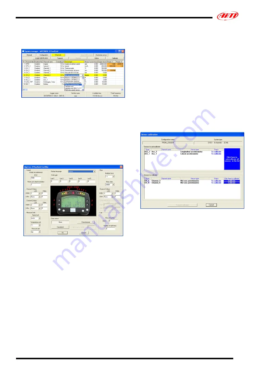
4) How to calibrate/autocalibrate the sensors
Once the configuration has been transmitted to the PC you
have to calibrate/autocalibrate the sensors.
The internal lateral accelerometer and the “potentiometer
distance” need to be autocalibrated, while “Mid zero
potentiometer”, “zero based potentiometer” and the “on-
board gear sensor” need to be calibrated.
Please press “calibrate” button and it will appear the
following screenshot.
Please follow these instructions:
•
The G-force sensor and the “potentiometer distance”
sensor need to be autocalibrated pressing button
“Click here to autocalibrate all sensors in the list”.
•
To calibrate the “on-board” gear sensor, the “Mid
zero potentiometer” or the “zero based
potentiometer”, please click on the corresponding
“Calibrate” button and follow the instructions
prompted on your PC’s monitor.
It is reminded that the calibration/autocalibration
procedure is fundamental in order to acquire correct
data.
5) Re-transmit the configuration
Once the calibration/autocalibration has finished, it is
absolutely necessary to re-transmit the configuration to your
MyChron 3 XG
pressing the “Transmit” button.
Technical documentation:
MyChron 3 XG
3


