7
- Pulse 3a: Vs = -220 V
- Pulse 3b: Vs = +150 V
- Formerly pulses 5a and 5b
• ISO 16750
-2 - Tests A and B
4.
Installation
A PDM manages current values that may be rather high, and its temperature strictly depends upon the
total load current. It must be installed in an aerated area and far from hot parts.
5.
Status LEDs
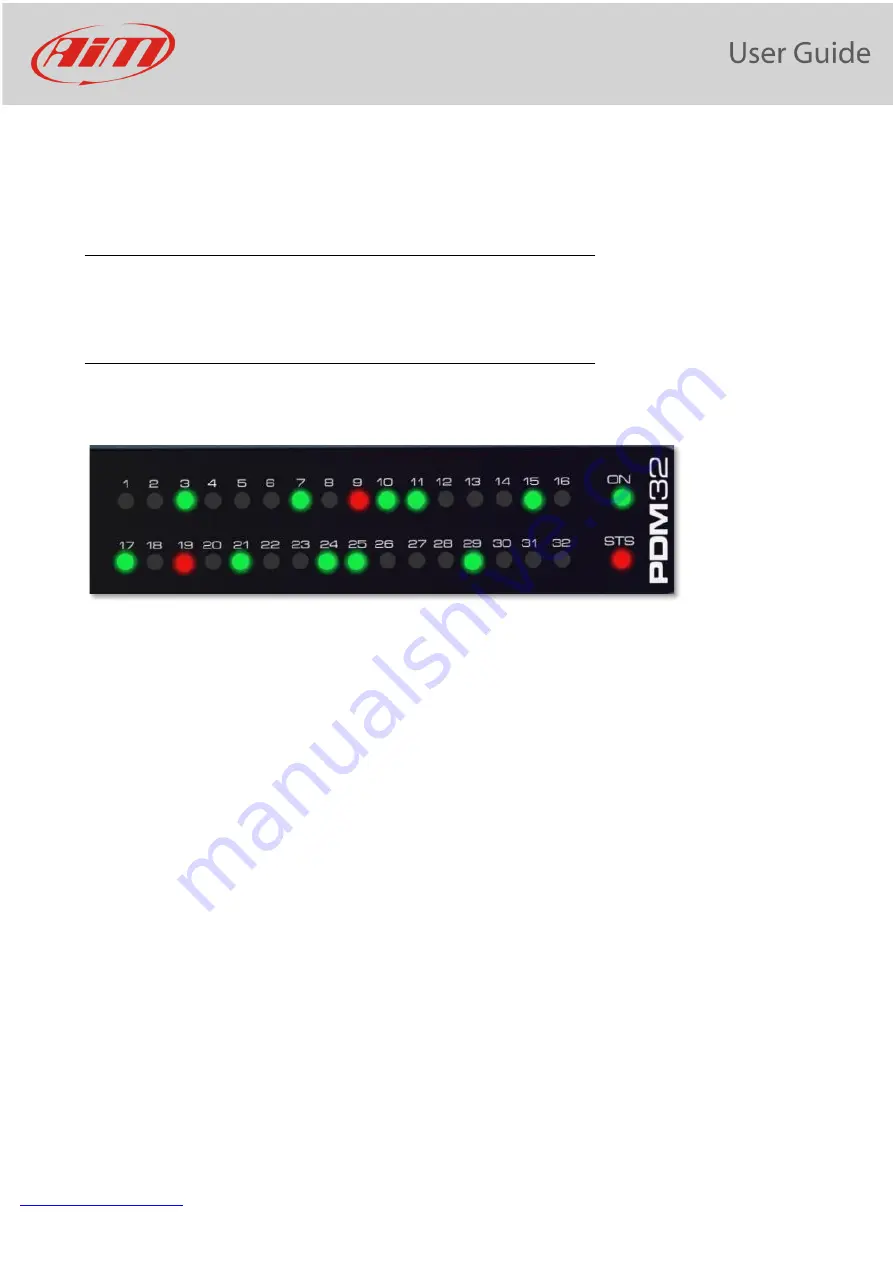
The PDM 32 has 32 status LEDs, one for every power output:
-
•
GREEN: the output is enabled, and its status is OK
•
RED: the output status is in alarm mode i.e. short circuit, open load, etc...
•
OFF: the output is not active.
There are also 2 additional LEDs: ON and STS (Status).
ON is green when PDM is active.
STS may be:
•
GREEN: everything is OK.
•
YELLOW SOLID:
•
Ext battery voltage value is between 9V and 11V or between 15V and 16V
•
Internal temperature of PDM is between 70°C and 85°C
•
RED SOLID:
•
Ext battery voltage value is between 8V and 9V or over 16V
•
Internal temperature of PDM is over 85°C
•
Any of internal peripheral not working properly
•
RED BLINKING:
•
Ext battery voltage value is under 8V. This causes power outputs to be disabled to avoid system
malfunction.
Summary of Contents for PDM 32
Page 1: ...PDM 32 User Manual VER 1 06 ...
Page 42: ...www aim sportline com PDM 32 User Guide 41 ...
Page 61: ...www aim sportline com PDM 32 User Guide 60 Appendix A Connectors and Pinout ...
Page 62: ...www aim sportline com PDM 32 User Guide 61 ...
Page 63: ...www aim sportline com PDM 32 User Guide 62 Appendix B Mechanical Drawings ...


