background image


October 2006


1

 -


Tools Needed for Repair 


US-LT Drivers


  1.  Phillips Drivers (#1 & #2) 


 2. Dental 

Pick 


 3. Pin 

Spanners 

(#351) 


 4. Needle 

Nose 

Pliers 


 5. Pin 

Punch 


  6.  Ball Peen Hammer (8 oz.) 


 7. Standard 

Pliers 


  8.  Snap Ring Pliers 


 9. Crescent 

Wrench 


  10.  Lock Ring & Horseshoe Washer Pliers (Proto-P250) 


  11.  Propane Torch (Turner Self-Lighting) 

Summary of Contents for Lite-Touch Series

Page 1: ...PO Box 16460 Portland OR 97292 0460 z 503 254 6600 z Fax 503 255 2615 Lite Touch Series Pneumatic Screwdriver Repair Manual ...

Page 2: ......

Page 3: ...w of the Gear Casing Assembly US LT30B 11 Series 7 US LT20B 18 7 US LT Series 8 7 Disassembly and Reassembly of the Air Motor Section 9 8 Exploded View of the Air Motor Assembly US LT Push to Start Series 10 US LT Pistol Series 11 US LT Lever Series 12 9 Disassembly and Reassembly of the Angle Head Section 13 10 Exploded View of the Angle Head Assembly US LT Series 14 11 LT Series Troubleshooting ...

Page 4: ... 1 Phillips Drivers 1 2 2 Dental Pick 3 Pin Spanners 351 4 Needle Nose Pliers 5 Pin Punch 6 Ball Peen Hammer 8 oz 7 Standard Pliers 8 Snap Ring Pliers 9 Crescent Wrench 10 Lock Ring Horseshoe Washer Pliers Proto P250 11 Propane Torch Turner Self Lighting ...

Page 5: ...US LT Series Jig List Jig to Insert the Band on the Anvil Part Number Model Number 471 670 7 1 US LT Series Jig to Hold Tool for Disassembly Reassembly Part Numbers Model Numbers 459 025 1 0 US LT10 US LT20 408 025 1 0 US LT30 US LT40 444 025 4 0 US LT50 ...

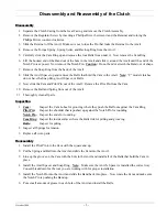
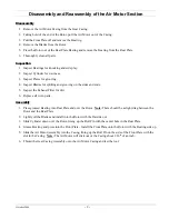
Page 6: ...Pilot Pin out of the Anvil Remove the Pilot Pin from the Cam 10 Remove the Ball and Spring from out of the Anvil 11 Thoroughly clean all parts Inspection 1 Cam Inspect the Cam Lobes for grooving where they push the Ball out against the Cam Ring Pilot Pin Inspect the shoulder that is pushed up against the Notch Pin for rounding Notch Pin Inspect the ends for rounding Cam Ring Inspect the inside sur...

Page 7: ...he Back up Ring and Spring Retainer down onto the Cam 9 Install the Torque Spring and Retainer onto the Anvil 10 Line the slot in the Anvil with the slot in the Retainer and install the Locking Pin 11 Thread the Regulator Screw onto the Anvil counter clockwise 12 Install the Clutch back into the tool and test ...

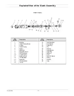
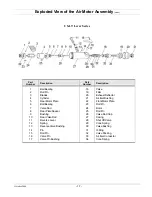
Page 8: ...4 15 Bushing Clutch Casing Sleeve O Ring Clutch Casing Spring Bit Sleeve Regulator Screw 3 32 Steel Ball Torque Spring Back up Ring 1 8 Steel Ball Notch Pin 3 16 Steel Ball G Pin 16 17 18 19 20 21 22 23 24 25 26 27 28 3 32 Steel Ball Anvil Spacer Snap Ring Pin Retainer Spring Setter Cam Ring Bit Band Anvil Notch Pin Band Spring Pilot Pin Cam ...

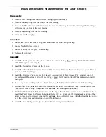
Page 9: ... of Planet Gears Put a small amount of grease by each Planet Gear and on the Gear Cage 4 Install the First Gear Cage Needle Rollers and the second set of Planet Gears Put a small amount of grease by each Planet Gear and on the Gear Cage Note On the mid and low RPMs make sure to install the Spacer 5 If the tool you are working with has a Rotor Gear install the Rotor Gear and Spacer into the Gear Ca...

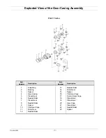
Page 10: ...oded View of the Gear Casing Assembly US LT30B 11 Series US LT20B 18 Part Number Description Part Number Description 1 2 3 4 Gear Casing Needle Roller Planet Gear Gear Cage 5 6 7 8 Ball Bearing Spacer Spacer Internal Gear ...

Page 11: ...3 4 5 6 7 8 9 10 11 12 Snap Ring Bearing Spacer Gear Casing Planet Gear Needle Roller Planet Gear Needle Roller Spacer First Gear Cage Rotor Gear Needle Roller 13 14 15 16 17 18 19 20 21 22 23 Needle Roller Rotor Gear Spacer First Gear Cage Second Gear Cage Planet Gear Planet Gear Gear Cage Planet Gear Needle Roller Spacer ...

Page 12: ...sides and ends 5 Inspect the Exhaust Filter for dirt 6 Replace all worn parts Assembly 1 Press greased Bearing into Rear Plate and over the Rotor Note There should be a slight drag between the Rotor and the Rear Plate 2 Lightly oil the Blades and install into the Rotor with the flat side out 3 Slide Cylinder down over the Rotor lining up the Roll Pin with the center hole in the Rear Plate 4 Grease...

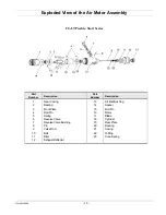
Page 13: ...art Number Description 1 2 3 4 5 6 7 8 9 10 11 12 Gear Casing Bearing Front Plate Roll Pin Spring Reverse Valve Reverse Valve Bushing Pin Valve Rod Ball Filter Exhaust Deflector 13 14 15 16 17 18 19 20 21 22 23 Air Inlet Bushing Spacer Roll Pin Rotor Blade Cylinder Rear Plate Bearing Casing O Ring Cone Spring ...

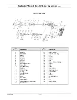
Page 14: ...l Pin Bearing Rear Plate Spacer Valve Rod Handle Bushing Packing Shut off Valve O Ring Handle Casing Roll Pin Rotor Rear Plate Valve Lever Allen Head Dog Point Screw Reverse Lever 21 22 23 24 25 26 27 28 29 30 31 32 33 34 35 36 37 38 39 Reverse Valve Valve Rod Bushing Pin Roll Pin Spring Ball Reverse Valve Bushing O Ring Ball Valve Cone Spring Inner Snap Ring Exhaust Stack Filter O Ring Air Inlet ...

Page 15: ...otor Plate Ball Bearing Valve Rod Rear Plate Spacer Bushing Rear Valve Rod Reverse Lever Spring Reverse Valve Bushing Pin Roll Pin Valve Pin Valve Pin Bushing 18 19 20 21 22 23 24 25 26 27 28 29 30 31 32 33 34 Valve Filter Exhaust Deflector Air Inlet Bushing Front Motor Plate Roll Pin Rotor Roll Pin Valve Rod Cap Casing Shut Off Valve Cone Spring Valve Bushing O Ring Valve Packing Air Inlet Connec...

Page 16: ... all Bearings for side play and knocking 3 Inspect the Driven Gear Spindle for side wear 4 Replace all worn parts Assembly 1 Set the Driven Gear into the Angle Head Casing Cover and install the Balls around the Driven Gear 2 Install the Driven Gear into the Angle Head Casing and secure by threading the Angle Head Casing Cover into the Angle Head Casing 3 Put a small amount of grease on the Driving...

Page 17: ...ll 1 8 Steel Ball Driven Gear Driven Gear Spindle Round Plate Angle Casing Driving Gear Needle Roller Bearing Snap Ring Adjusting Spacer Ball Bearing Bit Band 15 16 17 18 19 20 21 22 23 24 25 26 27 28 Needle Roller Bearing Driven Gear 1 8 Steel Ball Spring Angle Head Casing Cover Adjusting Spacer 1 16 Steel Ball Spacer Locking Nut Snap Ring Needle Roller Bearing Clutch Casing Sleeve O Ring Clutch ...

Page 18: ...o long Bur on Pilot Pin or inside of Cam Shorten Valve Rod Clean bur off of Pilot Pin or Cam Loss of RPMs Exhaust Filter is dirty causing back pressure Replace Filter Lever type only Tool will not run The Valve Rod is pushed through the Shut off Valve Replace Shut off Valve Tool runs all the time O ring has gotten pushed down into the Casing Air pressure is too high Put the O ring back into its se...

Page 19: ...October 2006 16 Recommended Preventative Maintenance It is recommended that the whole tool be cleaned and inspected every 250 000 cycles or six months whichever occurs first ...

Page 20: ...ones Prieto 2110 Pte Troy MI 48083 Portland OR 97216 Col Loma Larga 248 583 1180 800 852 1368 Monterrey NL CP 64710 Mexico FAX 248 583 7115 FAX 800 582 9015 011 52 81 1001 1600 www aimco global com FAX 011 52 81 1001 1630 LIT MAN410 Rev 08 2009 Printed in USA 2009 AIMCO ...

Reviews: