6
2
B
A
C
3
E
D
F
5
K
J
L
8
U
T
V
4
H
G
I
6
N
M
O
1
0
9
Y
X
W
Z
7
R
Q
P
S
2
B
A
C
3
E
D
F
5
K
J
L
8
U
T
V
4
H
G
I
6
N
M
O
1
0
9
Y
X
W
Z
7
R
Q
P
S
PS24
PS24
PS24
PS24
PS24
DP
DP
PS24
PS24
PS24
PS24
*2
*2
*2
*3
*2
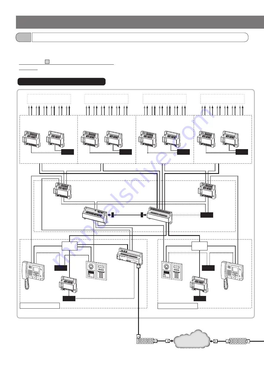
The following is a multi building system confi guration example that consists of expanded systems as tenant and main sections.
Refer to the installation manual
GT SYSTEM/Standard & Expanded System
for details about the expanded system confi guration.
Sub trunk line 1A
Sub trunk line 1B
Sub trunk line 2A
Sub trunk line 2B
Expanded video bus
control unit
GT-VBX
Expanded bus
control unit
GT-BCXB-N
Video bus
control unit
GT-VBC
GT-VBC
GT-VBC
GT-VBC
Bus control
unit
GT-BC
GT-BC
GT-BC
GT-BC
GT-BC
GT-VBC
[EXP]
GT-VBC
[EXP]
GT-BC
Entrance station
(Modular type and
all-in-one type enabled)
Entrance station
(Modular type
and all-in-one
type enabled)
GT-MKB-N
Guard
station
GT-MKB-N
Multi-building
control unit
GT-MCX
*
4
Common trunk line 1
Common trunk line 2
LAN
SYSTEM CONFIGURATIONS
Multi building consisting of expanded systems
1-3
Tenant section (expanded system)
*4:
The multi-building control unit GT-MCX must be connected to
common trunk line 1.
Switching hub
Switching hub
*1: Refer to Standard & Expanded System Manual about
residential/tenant station confi gurations.
*2: Make sure that a power supply is shared between GT-BC and
GT-VBC (STD). Also, a power supply must not be shared
between trunk lines (including sub and common trunk lines).
*3: Make sure that a power supply is shared between GT-BCXB-N
and GT-VBC.
* Refer to section
4
"WIRING" for details about wiring and
connection.
[Max. 125 stations
(max. 25 per trunk)] *1
[Max. 125 stations
(max. 25 per trunk)] *1
[Max. 125 stations
(max. 25 per trunk)] *1
[Max. 125 stations
(max. 25 per trunk)] *1


