4
4
WIRING
– 4 –
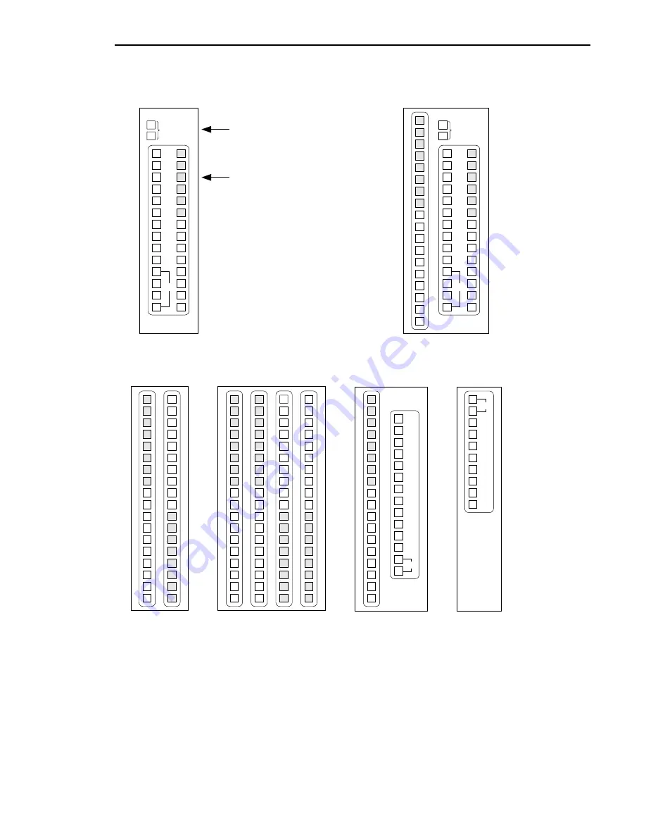
Terminal-block layout
Meaning of terminal symbols
E terminal
is common calling and communication line.
No. 1~40 terminals
are selective station points, providing selective calling and communication.
C & M terminals
are master-to-master communication.
R & T terminals
are master-to-door adaptor transmit and receive lines.
S & S terminals
are call tone output to IER-2 call extension speaker.
Cable requirements
Use 2-conductor cable (twisted or non-twisted) homerun to each sub station (0.65 ~ 1.0mm
φ
,
22 ~ 18AWG).
+
−
+
−
TC-10M
Each E terminal may have
one to three wires from
TB-SE terminal 2.
2 wires from TB-SE subs must
not be made common at any
other point than on the
TC-M terminal block.
1
12V
2
3
4
5
6
7
8
9
10
E
E
E
E
E
E
C
M
R
R
T
T
S
S
1
12V
2
3
4
5
6
7
8
9
10
+
−
+
−
E
E
E
E
E
E
C
M
R
R
T
T
S
S
DC18V or
AC15-16V
E
E
E
E
E
E
E
E
20
19
17
16
18
15
13
12
14
11
TC-20M
DC18V or
AC15-16V
Connect power supply to
TC-M Master station
(Max. 25m/1.0mm
φ
, 80
´
/18AWG)
★
1
12V
2
3
4
5
6
7
8
9
10
+
−
E
E
E
E
E
E
E
E
D10
D9
D7
D6
D8
D5
D3
D2
D4
D1
TB-AD10
E
E
E
E
E
E
E
E
20
19
17
16
18
15
13
12
14
11
1
2
3
4
5
6
6
8
9
10
E
E
E
E
E
E
E
E
TC-20G
E
E
E
E
E
E
E
E
40
39
37
36
38
35
33
32
34
31
E
E
E
E
E
E
E
E
30
29
27
26
28
25
23
22
24
21
11
12
13
14
15
16
17
18
19
20
E
E
E
E
E
E
E
E
1
2
3
4
5
6
7
8
9
10
E
E
E
E
E
E
E
E
TC-40G
R
T
12V
2
+
−
TB-AD1
R
T
N
1


