air
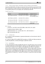
avionics
1. General Description
1.4.3 Hardware
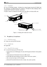
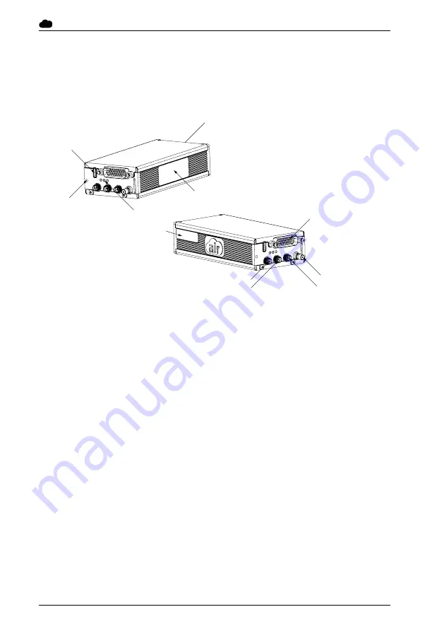
AT-1 has an all-metal housing. It features two power/signal connectors (D-SUB), four
RF connectors, an optional static port connector, a USB port for data exchange, and an
integrated WiFi antenna for wireless connectivity.
The device status is presented using three multi-color LEDs on the back of the unit.
Device Label
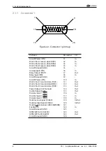
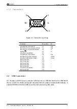
Connector 2 (D-SUB 15HD)
Connector 1 (D-SUB 26HD)
3 Status LED
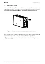
Static Port
USB Connector
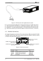
GPS Antenna Connector (QMA)
1090MHz Antenna Connector (rpSMA)
FLARM Antenna Connector A (SMA)
FLARM Antenna Connector B (SMA)
WiFi Antenna
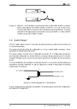
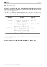
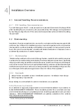
Figure 1.2.: Housing and connector overview
1.5 Regulatory Compliance
1.5.1 ETSO Functions
AT-1 does not cover any ETSO functions.
1.5.2 Deviations
Not applicable.
1.5.3 Non-ETSO Functions
AT-1 covers the following non ETSO functions:
•
Sends and receives FLARM signals. Receives ADS-B signals and Mode-S transponder
replies.
•
Computes threat information for received traffic signals.
•
Sends traffic data and warnings to other cockpit- and avionics systems.
•
Puts out aural warnings and info messages.
•
Delivers GPS data (SIL/SDA=0) to other cockpit- and avionics systems.
AT-1
·
Installation Manual
·
rev. 4.0
·
2020/01/09
3

