
air
avionics
3. Interfaces
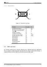
Pin Name
Pin number
I/O
Aircraft Power
1.1/1.10
In
Aircraft Ground
1.5/1.9/1.23/1.26
–
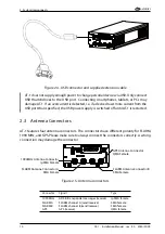
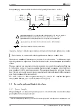
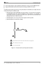
We recommend the installation of a 3A manually resettable circuit breaker in the power
supply line, e.g. a
Sensata Klixon 7277-2-3
. Using such a circuit breaker ensures that the
AT-1 can be switched off by the flight crew if required. Additionally, in the case of a
non-permanent malfunction the power supply can be restored. The circuit breaker shall be
clearly labeled.
Connection of the input power to incorrect pins can cause damage to the unit that
will require return to the factory for repair. Ensure that the power supply is connected
to the correct pins and does not short to any adjacent pins prior to applying power to
the unit.
3.5.2 Power Output
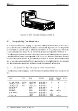
Connector 2 features a supply power output. The output pins directly connect to the VIN
pins on connector 1. Its main intention is to supply an AIR Traffic Display (ATD-11, ATD-57,
or ATD-80) if the AT-1 is directly attached to such a display.
Pin Name
Pin number
I/O
Power Output
2.1/2.6
Out
Ground (GND)
2.5/2.14
–
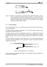
3.5.3 Enable Interface
Both connectors feature a pin that enables power when pulled to ground/low. For AT-1 to
power up, at least one of these two pins must be connected to ground (GND). Active-Low
discrete inputs like the Enable Interface are considered active if either the voltage to ground
is below a certain minimum or if the resistance to ground is below approximately 300 Ohms.
Pin Name
Pin number
I/O
Enable
1.22/2.4
In (Active Low)
If the AT-1 is installed in combination with an AIR Traffic Display (ATD-11, ATD-57, or ATD-80),
the pin is automatically pulled to ground/low when the ATD is powered up.
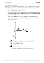
An external switch can be connected if AT-1 is to be switched on/off manually.
AT-1
·
Installation Manual
·
rev. 4.0
·
2020/01/09
15