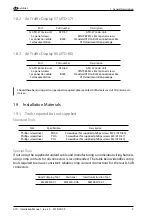
2. System Interconnects and Interfaces
air
avionics
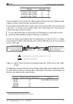
Serial Input Protocol
ATD accepts ‘‘extended NMEA’’ GPS and traffic data as well as GARMIN TIS traffic data. For a
detailed description of supported datasets, please contact AIR Avionics customer support.
ATD accepts different data rates. ATD-57 automatically adjusts to the current data rate
present on its serial inputs, if one of the following:
•
4800 baud
•
9600 baud
•
19,200 baud
•
28,800 baud
•
38,400 baud
•
57,600 baud
2.3 Power and Lighting Functions
This section covers the power input requirements and lighting bus input.
2.3.1 Power Supply
Power inputs on connector 1 and connector 2 provide power. All pins of one connector
should be connected. If required, pins on both connectors may be connected.
Connector 1 and connector 2 power pins are internally decoupled. Therefore different
supply voltages on the two connectors are acceptable, e.g. if a backup battery is connected
to one of the two connectors.
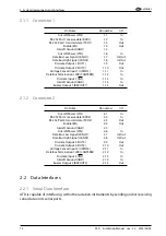
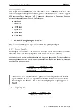
Pin Name
Pin number
I/O
Aircraft Power
1.1/1.6 or 2.1/2.6
In
Aircraft Ground
1.5 or 2.5
–
Connection of input power to incorrect pins can cause damage to the unit that will
require return to the factory for repair. Ensure that the power supply is connected to
the correct pins and does not short to any adjacent pins prior to applying power to
the unit.
2.3.2 Lighting Bus
Pin Name
Pin number
I/O
Lighting Bus
1.11 or 2.11
In
14
ATD
·
Installation Manual
·
rev. 3.0
·
2019/05/09


