7
Ground Checks
7.1 Interface Checkout
7.1.1 Serial Interface
The serial data interface of the unit can be checked with a pragmatic function test.
1. Connect ATD and another compatible avionics system via a serial data port.
2. Verify correct operation.
7.2 Controls
This check verifies that all controls operate correctly.
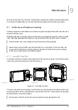
1. Manipulate all pilot controls ( buttons 1, 2, 3, and 4 , the concentric rotary knob ,
and the inner knob pushbutton ). Please consult the ATD Pilot’s Manual for details
on pilot controls.
2. Check if manipulation results in control input on the display.
Depending on the unit’s configuration and software status not all controls may be active all the time.
7.3 Lighting
7.3.1 Lighting Bus
The display and bezel key backlight on ATD can track an external lighting bus input and use
it to vary the display and bezel key illumination levels accordingly.
Connection of the aircraft lighting bus to the incorrect input pins can cause damage.
Always start this test with the lighting bus at the lowest setting, and slowly increase
the brightness. If it is noticed that the lighting level on the display does not increase
as the lighting bus input is increased in brightness, verify that the wiring is correct
before proceeding.
This check verifies that the interface is connected correctly.
1. Ensure the lighting bus is set to its minimum setting.
2. Slowly vary the lighting bus level that is connected to ATD. Verify that the display
brightness tracks the lighting bus setting. Continue to maximum brightness and
verify proper operation.
30
ATD
·
Installation Manual
·
rev. 3.0
·
2019/05/09

