background image

CAUTION:


MAKE SURE POWER IS SWITCHED OFF AT

SERVICE PANEL BEFORE STARTING INSTALLATION.

NOTE:

 If a light fixture is being installed with the fan, follow the

fixture’s owner’s manual for wiring. This fan is adaptable to center-
mount light kits only.
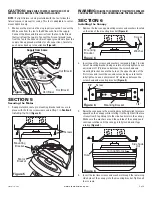
1.

Make sure the electrical box is properly secured. Connect the
White wire from the fan to the White wire from the supply.
Connect the Black and Blue wires from the fan to the Black
(hot) wire from the supply. Connect the Green (ground) wire
from the fan to the Green or Bare Copper ground wire from the
supply. Use approved methods for all connections. Carefully
push wires back up into outlet box 

(Figure 4)

.

SECTION 5

Securing the Motor

1.

Swing motor bracket up to mounting bracket and secure in
place with the three screws removed in 

Step 1

 in 

Section 3

Installing the Fan


(Figure 5)

.

WARNING:


FAILURE TO COMPLETELY TIGHTEN THE SCREWS

COULD RESULT IN THE FAN LOOSENING AND POSSIBLE FAILING.

SECTION 6

Installing the Canopy
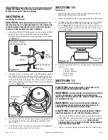
1.

Remove the four canopy mounting screws and washers located
on the side of the mounting bracket 

(Figure 6)

.

2.

Insert one of the screws and washers removed in Step 1 in side
hole of mounting bracket, being careful not to fully tighten. Leave
a minimum of 1/8" distance between the screw head and
mounting bracket. Locate the hole on the opposite side of the
first screw and insert the second screw, being careful not to
fully tighten. Leave a minimum of 1/8" distance between the
screw head and mounting bracket 

(Figure 5)

.

3.

Raise the canopy up to the mounting bracket. Apply light pressure
upward on the canopy while rotating it to the right until the two
screws from Step 2 drop into the side hook slots in the canopy.
Make sure the washers are on the outside of the canopy and
continue rotation until the canopy is fully locked and stops
rotating 

(Figure 5)

.

4.

Insert the last two screws and washers through the remaining
side holes of the canopy into the mounting bracket. Tighten all
four screws.

www.airkinglimited.com

9842 Rev A. 9-05

3 of 8

1/8"

Side hook

slot

Hole

Turn right to lock

Figure 4

Ground

Hot (Black)

White

Supply from home

Hot (Black)

from fan

Hot (Blue)

Figure 5

Screws

Motor

Bracket

Mounting

Bracket

Screw

Mounting
Bracket

Figure 6

Washer

Figure 6

1/8"

Screw

Mounting Bracket

Figure 6

Summary of Contents for 9842

Page 1: ...iring must be done by qualified person s in accordance with all applicable codes and standards including fire related construction CAUTION THIS FAN MUST NOT BE USED IN POTENTIALLY DANGEROUS LOCATIONS SUCH AS FLAMMABLE EXPLOSIVE CHEMICAL LADEN OR WET ATMOSPHERES 5 Make certain that the power source conforms to the electrical requirements of the fan 6 The fan must be hung with at least 7 feet of cle...

Page 2: ...ack fan from the carton and confirm that all pieces are present The following should be present 1 Motor assembly 4 Blades 4 Blade mounting brackets 1 Hanger bracket 1 Canopy 1 Package containing 12 1 2 washer head screws 12 paper washers 1 pull cord 2 8 32 machine screws 1 Instruction Safety Sheet NOTE Extra hardware is included in parts bag 2 Install mounting bracket to the electrical box marked ...

Page 3: ...he side of the mounting bracket Figure 6 2 Insert one of the screws and washers removed in Step 1 in side hole of mounting bracket being careful not to fully tighten Leave a minimum of 1 8 distance between the screw head and mounting bracket Locate the hole on the opposite side of the first screw and insert the second screw being careful not to fully tighten Leave a minimum of 1 8 distance between...

Page 4: ...12 Screws Hole Blade and Bracket SECTION 10 Operation 1 Restore electrical power to the electrical box by turning the electricity on at the main service panel 2 Check the operation of the fan by gently pulling the chain switch 3 If airflow is desired in opposite direction turn your fan off and wait for the blades to stop turning then slide the reversing switch Figure 13 to the opposite position an...

Page 5: ...ely to left or right 2 Fan sounds noisy 1 Screws securing fan brackets to motor housing are loose 1 Check to be sure screws are tight 2 Wire nuts in side switch housing are rattling 2 Check wire nut connections in switch housing 3 Fan wobbles or shakes 1 Screws securing fan blade brackets to motor housing 1 Check to be sure screws are tight excessively are loose 2 Fan blade brackets not seated pro...

Page 6: ... date of purchase place of purchase and model purchased Failure to meet these requirements will void your warranty Air King will not be held responsible for any bodily injury or damages to personal property or real estate whether caused directly or indirectly by the product Some states and provinces do not allow the exclusion or limitation of incidental or consequential damages and some states do ...

Page 7: ...EPLACEMENT PARTS DIAGRAM Qty Description 1 1 Mounting Bracket 2 4 Screw 3 3 Screw 4 1 Motor 5 1 Canopy 6 12 Washer Head Screw 7 12 Paper Washer 8 4 Paddle 9 4 Paddle Bracket 10 8 Pan Head Screw 11 1 Pull Chain 1 2 3 4 7 5 8 11 6 2 3 6 9 7 8 9 10 10 ...

Page 8: ...www airkinglimited com 9842 Rev A 9 05 8 of 8 ...

Reviews: