

CAUTION:
MAKE SURE THAT THE ELECTRICAL WIRES ARE
COMPLETELY INSIDE THE ELECTRICAL BOX AND NOT PINCHED
BETWEEN THE CANOPY AND THE CEILING.
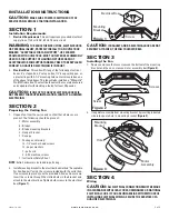
SECTION 9
Installing Fan Blades
CAUTION:
THE BLADES SHOULD BE ATTACHED TO THE
FAN MOTOR AFTER IT IS HUNG AND WIRED. IF THE BLADES ARE
ATTACHED WHILE THE MOTOR IS ON THE FLOOR, THE BLADES
COULD GET BENT, CAUSING THE FAN TO WOBBLE.
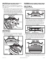
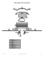
1.
Using three #10-32x1/2" Phillips washer head screws and three
paper washers, secure one bracket to each of the blades.
Complete this assembly before attaching blades to the ceiling
fan
(Figure 11)
.
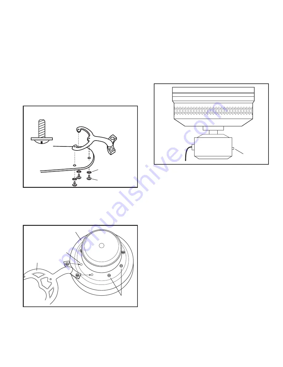
2.
Using the screws on the motor hub, install the blade and blade
bracket to the hub by removing two of the screws, then place
one of the screws into the recessed hole in the blade bracket
and up into the hole in the motor hub. Turn screw until it mates
with the threaded hole in hub. Do not tighten screw completely
at this time
(Figure 12)
.
4.
Install the second screw in the same manner, then tighten both
screws firmly. Install the remaining blade assemblies in the
same manner.
5.
Install the fans pull cord chain by connecting the included ball
and string to chain coming from fan’s motor.
www.airkinglimited.com
9842 Rev A. 9-05
4 of 8
#10-32x1/2" Phillips
Washer Head Screw
Blade
Bracket
Blade
Screws
Figure 11
Paper Washers
Motor Hub
Figure 12
Screws
Hole
Blade and
Bracket
SECTION 10
Operation
1.
Restore electrical power to the electrical box by turning the
electricity on at the main service panel.
2.
Check the operation of the fan by gently pulling the chain switch.
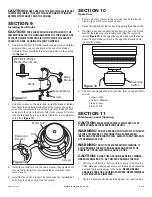
3.
If airflow is desired in opposite direction, turn your fan off and
wait for the blades to stop turning, then slide the reversing
switch
(Figure 13)
to the opposite position, and turn the fan on
again. The fan blades will turn in the opposite direction and
reverse the airflow.
4.
This unit is equipped with a four position, three speed pull chain
switch:
1st pull = High
2nd pull = Medium
3rd pull = Low
4th pull = Off
SECTION 11
Maintenance and Cleaning
CAUTION:
MAKE SURE POWER IS SWITCHED OFF AT
SERVICE PANEL BEFORE SERVICING THE UNIT.
WARNING:
DO NOT DEPEND UPON THE FAN’S CONTROLS
AS THE SOLE MEANS OF DISCONNECTING POWER WHEN
INSTALLING OR SERVICING THE FAN. ALWAYS TURN POWER OFF
AT THE MAIN FUSE BOX.
WARNING:
DO NOT USE WATER WHEN CLEANING. IT
COULD DAMAGE THE MOTOR OR BLADES AND CREATE THE
POSSIBILITY OF AN ELECTRICAL SHOCK OR FIRE.
CAUTION:
DO NOT USE GASOLINE, BENZINE, THINNER,
HARSH CLEANSERS, ETC., AS THEY MAY DAMAGE THE FAN.
1.
Use only a soft brush or lint free cloth to avoid scratching the
finish. Abrasive cleaning agents are not required and should be
avoided to prevent damage to the finish.
NEVER USE ANY
ABRASIVE PADS OR SCOURING POWDERS.
NEVER IMMERSE
ELECTRICAL PARTS IN WATER.
2.
The fan is permanently lubricated and does not require oiling.
Reversing
Switch
Figure 13


