background image

Designed for cooling workers in factories, warehouses, manufacturing facilities and garages where 
humid and demanding conditions exist. All circulator heads have high efficiency corrosion resistant 
propellers with steel blades. Circulator heads utilize a vertical tilt/locking adjustment for directional 
flow. Wire guards are black power-coated steel and comply with OSHA Standard 1910.212 (1/2” 
maximum opening). All circulator heads are oscillating that sweep through a 45

° 

or 90

°

 arc.

               2

Operating Instructions & Parts Manual                                                           Models: 99538, 99539

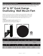
24” & 30” Quiet Design 

Oscillating  Wall Mount 

Fan

Unpacking

1. Inspect for any damage that may have occurred during transit.

2. Shipping damage claim must be filed with carrier.

3. Check all bolts, screws, setscrews, etc. for looseness that 

may have occurred during transit. Retighten as needed.

Oscillating Dimensions and Specifications


99539 


24” 

    20 1/4”          26 3/4”           120 

       60 

                3 

      3   


Wall Mount                                  

99538 


30” 

    20 1/4”          33 3/8”           120 

       60                     3 

      3 


Wall Mount                                  


       2


              Prop.    

Model 

               Dia. 

        A 

             B                Volts               Hz                Speeds          Blades             Mounting Accessory 


 99539 

      24”      1025/880/480          1/4      5030       4320      2280           500/350/220            7.7/5.7/1.8               2.3/1.6/0.6                     3.5                

 99538           30”      1010/860/530          1/4      7450       6090      3450           700/520/300            6.7/5.4/2.0               2.3/1.6/0.6                     3.7               


     Prop.         Motor      

                            CFM 

            Air Velocity                Sones @              Operating              Full Load 


 Model       Dia.            RPM                  HP         High      Med     Low          @ 20 Ft. (FPM)              0.000SP                   Amps                      Amps

PLeASe ReAD AnD SAVe tHeSe InStRUCtIOnS.

 Read carefully before attempting to assemble, install, operate or 

maintain the product described. Protect yourself and others by observing all safety information. Failure to comply 

with instructions could result in personal injury and/or property damage! Retain instructions for future reference.

  Printed in U.S.A.    New 5/11

5085459

A

Summary of Contents for 99538

Page 1: ...ews setscrews etc for looseness that may have occurred during transit Retighten as needed Oscillating Dimensions and Specifications 99539 24 20 1 4 26 3 4 120 60 3 3 Wall Mount 99538 30 20 1 4 33 3 8 120 60 3 3 Wall Mount 2 Prop Model Dia A B Volts Hz Speeds Blades Mounting Accessory 99539 24 1025 880 480 1 4 5030 4320 2280 500 350 220 7 7 5 7 1 8 2 3 1 6 0 6 3 5 99538 30 1010 860 530 1 4 7450 609...

Page 2: ...NNECTION MAY CREATE THE RISK OF ELECTRICAL SHOCK USE OF SUCH ADAPTERS IS NOT PERMITTED IN CANADA 10 Where possible avoid the use of extension cords If they must be used minimize the risk of overheating by ensuring that they are UL listed Never use a single extension cord to operate more than one Fan Do not plug Fan into any other cord connected device such as a power strip cord reel surge protecto...

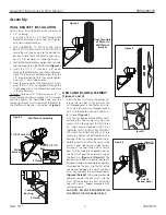
Page 3: ... WIRES ON THE FRONT OR THE REAR GRILLS Assembly WALL BRACKET INSTALLATION NOTE Always install the bracket to a minimum of 2 x 4 studding 1 Insert the 7 16 14 x 3 1 2 Bolt through Wall Bracket and into the 7 16 14 Lock Nut Tighten with Adjustable Wrenches 2 THE HARDWARE TO ATTACH THE WALL BRACKETTOTHEWALLSTUDISNOTSUPPLIED Locate the wall stud nearest to the desired Fan location Attach the Wall Brac...

Page 4: ...uts Make sure no part of the Cable interferes with the Blade 3 Wrap the other end of the Cable around a secure building joist truss or other support near the Fan Take up all excess slack in the Cable CAUTION USE ONLY THE MOUNTING HARDWARE WHICH IS RECOMMENDED FOR USE ON THIS FAN 4 AttachtheremainingCableClampasindicated in Step 2 The excess tail should be trimmed to extend 1 to 2 inches past the C...

Page 5: ...145 1 4 Rear Grill 5097022BK 5097012BK 1 5 Hardware Bag A 02098012 02098012 1 6 Hardware Bag B 05098022 05098022 1 7 Wall Mount Bracket 5062095BKT 5062095BKT 1 2 Ref Part Numbers for Models No Description 99539 24 99538 30 Qty For Repair Parts call 1 800 233 0268 Please provide following information Model number Serial number if any Part description and number as shown in parts list 5085459 1 3 2 ...

Page 6: ...NCLUDE I INCIDENTAL OR CONSEQUENTIAL DAMAGES FROM ANY CAUSE WHATSOEVER OR II REPLACMENT OR REPAIR OF ANY HOUSE FUSES CIRCUIT BREAKERS OR RECEPTACLES NOTWITHSTANDING ANYTHING TO THE CONTRARY IN NO EVENT SHALL AIR KING S LIABILITY UNDER ANY EXPRESS OR IMPLIED WARRANTY EXCEED THE PURCHASE PRICE OF THE PRODUCT AND ANY SUCH LIABILITY SHALL TERMINATE UPON THE EXPIRATION OF THE WARRANTY PERIOD Some state...

Page 7: ...____________________________________________________________________________ __________________________________________________________________________________ __________________________________________________________________________________ __________________________________________________________________________________ __________________________________________________________________________...

Page 8: ...8 New 5 11 5085459 ...

Reviews: