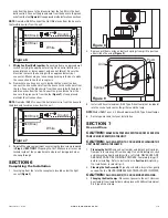
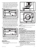
SECTION 3
Existing Construction
1.
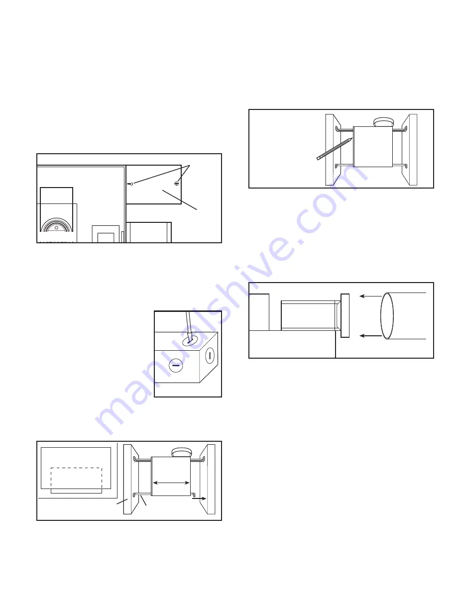
Set housing in position between the joist and trace an outline onto
the ceiling material
(Figure 4)
. Set housing aside and cut opening,
being careful not to cut or damage any electrical or other hidden
utilities. Install the rails on the housing and position the housing in
the previously cut hole so that it is flush with the finished ceiling.
Secure the ends of the rails to the joists with screws or nails (not
provided) to ensure proper installation
(Figure 3)
.
SECTION 4
Ducting
CAUTION:
ALL DUCTING MUST COMPLY WITH LOCAL AND
NATIONAL BUILDING CODES.
1.
Remove any tape that might be holding the damper in place during
shipping and connect the ducting to the fan’s duct collar (
Figure
5)
. Secure in place using tape or screw clamp. Always duct the
fan to the outside through a wall or roof cap.
SECTION 5
Wiring
CAUTION:
MAKE SURE POWER IS SWITCHED OFF AT SERVICE
PANEL BEFORE STARTING INSTALLATION.
CAUTION:
ALL ELECTRICAL CONNECTIONS MUST BE MADE
IN ACCORDANCE WITH LOCAL CODES, ORDINANCES, OR NATIONAL
ELECTRICAL CODE. IF YOU ARE UNFAMILIAR WITH METHODS OF
INSTALLING ELECTRICAL WIRING, SECURE THE SERVICES OF A
QUALIFIED ELECTRICIAN.
1.
Wiring Fan/Heat Bulb(s) Independently:
Run wiring from an
approved wall switch carrying the appropriate rating. One neutral
(white), one ground (green or bare copper), and two hot (black and
blue). Secure the electrical wires to the housing with an approved
electrical connector. Make sure you leave enough wiring in the
box to make the connection to the fan’s receptacle.
1a. From where you have access to inside the fan’s junction box,
connect the white wire from the house to the white wire from the
fan. Connect one hot (black) wire from the house to the black wire
from the fan (this is the fan control). Connect the second hot (blue)
INSTALLATION INSTRUCTIONS
CAUTION:
MAKE SURE POWER IS SWITCHED OFF AT SERVICE
PANEL BEFORE STARTING INSTALLATION.
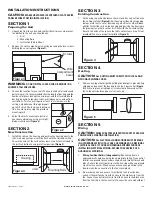
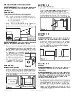
SECTION 1
Preparing the Unit
1.
Unpack fan from the carton and confirm that all pieces are present.
In addition to the unit you should have:
1 - Grill
4 - Mounting Rails
1 - Instruction/Safety Sheet
2.
Remove the wire compartment cover by loosening the two screws
holding the cover in place
(Figure 1).
WARNING:
DO NOT INSTALL OVER A TUB OR MOUNT IN A
SHOWER STALL ENCLOSURE.
3.
Choose the location for your unit. To ensure the best air and sound
performance, it is recommended that the length of ducting and the
number of elbows be kept to a minimum, and that insulated hard
ducting be used. Larger duct sizes will reduce noise and airflow
restrictions. This fan will require at least 6" of clearance in the
ceiling, and will mount through drywall
up to 3/4" thick. The fan mounts between
16" on center joists using the provided
mounting rails.
4.
Select the most convenient electrical
knockout and remove using a straight-
blade screw driver
(Figure 2)
.
SECTION 2
New Construction
1.
Install the rails on the housing and position the housing next to the
joist. Line up housing so it will be flush with the finished ceiling.
Secure the ends of the rails with screws or nails (not included) to
the joists and slide housing into final position
(Figure 3)
.
www.airkinglimited.com
210575917 Rev. A 1-06
2 of 8
Figure 4
Figure 5
Figure 1
Screws
Wire
Compartment
Cover
Figure 2
Figure 3
Joist
Housing
Mounting Rails


