2.
Remove grill from carton and attach springs from grill to posts on
either side of housing
(Figure 9)
.
5.
Install a 250 watt maximum, R-40 Type A heat lamp (not included)
into the socket and center the grill around the lamp.
NOTE:
Model AK927 uses 2 - 250 watt maximum R-40, Type A heat lamps.
6.
Restore power and test your installation.
SECTION 7
Use and Care
CAUTION:
MAKE SURE POWER IS SWITCHED OFF AT SERVICE
PANEL BEFORE SERVICING THE UNIT.
CAUTION:
ALLOW LAMP(S) TO COOL BEFORE CLEANING THE
UNIT OR REPLACING THE LAMPS.
1.
Cleaning the Grill:
Remove heat lamp(s) and detach grill springs
from posts to release grill from housing. Use a mild detergent, such
as dishwashing liquid, and dry with a soft cloth. NEVER USE ANY
ABRASIVE PADS OR SCOURING POWDERS. Completely dry grill
before reinstalling. Refer to instructions in
Section 6
Completing
the Installation, to reinstall grill.
2.
Cleaning the Fan Assembly:
Wipe all parts with a dry cloth or gently
vacuum the fan. NEVER IMMERSE ELECTRICAL PARTS IN WATER.
CAUTION:
ALLOW LAMP(S) TO COOL BEFORE REPLACING.
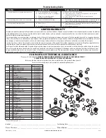
3.
Changing the Heat Lamps:
Disconnect power to the unit. Unscrew
heat lamp(s) from lamp holder and replace with 250 watt maximum,
R-40, type A heat lamp.
www.airkinglimited.com
210575917 Rev. A 1-06
3 of 8
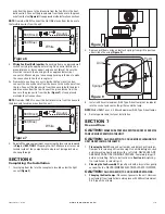
Figure 9
wire from the house to the blue wire from the fan (this is the heat
bulb control). Connect the ground wire from the house to the green
wire from the fan
(Figure 6)
. Use approved methods for all connections.
NOTE:
On model AK927 connect the Hot (Blue) wire from the house to
the two Blue wires from the unit.
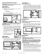
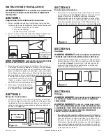
2.
Wiring Fan/Heat Bulb together:
Run wiring from an approved wall
switch carrying the appropriate rating. One neutral (white), one
ground (green or bare copper), and one hot (black). Secure the
electrical wires to the housing with an approved electrical
connector. Make sure you leave enough wiring in the box to make
the connection to the fan’s receptacle.
2a. From where you have access to inside the fan’s junction box,
connect the one white wire from the house to the white wire from
the fan. Connect the black wire from the house to both the black
and blue wires from the fan. Connect the ground wire from the
house to the green wire from the fan (
Figure 7)
. Use approved
methods for all connections.
NOTE:
On model AK927 connect the hot (black) wire from the house to
the black and two blue wires from the unit.
3.
Reinstall the wire compartment cover using the two screws removed
in
Step 2
of
SECTION 1
Preparing the Unit. Make sure all wires are
tucked inside of the compartment and are not being pinched or
showing through.
SECTION 6
Completing the Installation
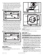
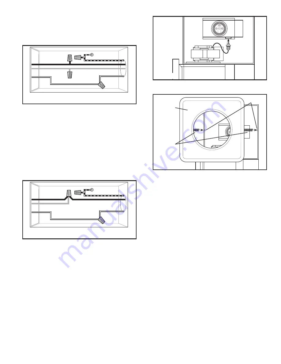
1.
Insert plug from fan into the receptacle located under the light
socket
(Figure 8)
.
Figure 6
Ground
Supply from house
White
Hot (Black)
From Fan
Hot (Blue)
Figure 7
Ground
Supply from house
White
Hot (Black)
From Fan
Hot (Blue)
Figure 8
Posts
Springs
Grill


