1b.
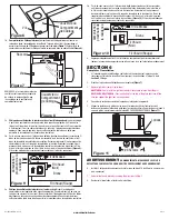
Internal Wire Compartment:
Remove the screw holding the blower assembly in place. Lift
up on the assembly and tilt it at a 45° angle to remove from the housing
(Figure 7).
Remove
the wire compartment cover screw and place the cover in a secure place
(Figure 8).
NOTE:
If the fan motor plug is
connected to the fan housing
receptacle, unplug so the
blower assembly can be
completely removed.
2a.
Wiring Fan/Light Independently:
Run wiring from an approved wall switch carrying the
appropriate rating. One neutral (white), one ground (green or bare copper), and two hot
(black lead connected to the switch). Secure the electrical wires to the housing with an
approved electrical connector. Make sure you leave enough wiring in the box to make the
connection to the fan’s receptacle.
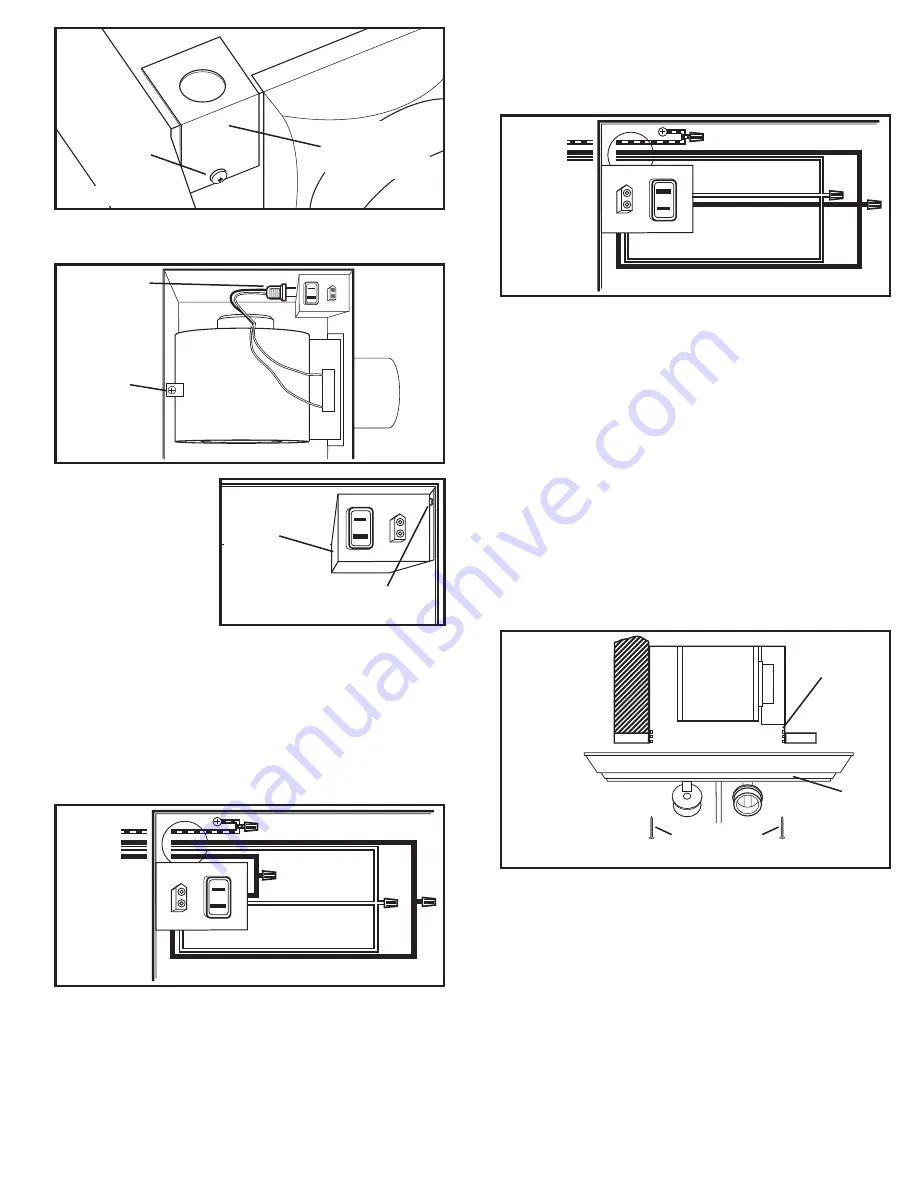
2b. From where you have access to inside the fan’s junction box, connect the one white wire
from the house to both the white wire from the fan’s light receptacle and the white wire
from the fan’s exhaust receptacle. Connect the first black wire from the wall switch to the
red wire from the fan’s light receptacle. Connect the second black wire from the switch to
the fan’s exhaust receptacle. Connect the ground wire from the house to the green wire
from the fan’s grounding screw
(Figure 9)
. Use approved methods for all connections.
3a.
Wiring Fan/Light together:
Run wiring from an approved wall switch carrying the
appropriate rating. One neutral (white), one ground (green or bare copper), and one hot
(black lead connected to the switch). Secure the electrical wires to the housing w ith an
approved electrical connector. Make sure you leave enough wiring in the box to make the
connection to the fan’s receptacle.
www.airkinglimited.com
A210572216 Rev. A 5-14
3 of 4
3b. From where you have access to inside the fan’s junction box, connect the one white wire
from the house to both the white wire from the fan’s light receptacle and the white wire
from the fan’s exhaust receptacle. Connect the black wire from the wall switch to both
the red wire from the fan’s light receptacle and the black wire from the fan’s exhaust
receptacle. Connect the ground wire from the house to the green wire from the fan’s
grounding screw
(Figure 10).
Use approved methods for all connections.
4. Carefully tuck wire back inside wire compartment and replace wire compartment cover
securing with the screw that was removed earlier.
SECTION 6
Completing the Installation
1. If the fan’s blower assembly was removed during the wiring process, reinstall the blower
by reversing the directions in
Step 1b
in
Section 5
Wiring
.
2. Insert the fan’s plug into the receptacle
(Figure 7)
.
3. Remove light lens from grill as follows:
AKLC70RCB:
Gently twist the light lens counter clockwise to release from the grill.
AKLC70SLN, AKLC70SLW:
Slide the glass light lens out either side of the grill.
AKLC70SNS, AKLC70DRSB:
Unscrew the finial at the top of the glass light lens. Make
sure you support the light lens as you unscrew.
4. Plug cord from lamp holders into the appropriate receptacle.
5. Line up slots in the grill with lances on inside of housing. Insert included #8 screws
through grill slots and into housing lances. Tighten both screws until the grill fits snugly
to the ceiling. DO NOT OVER TIGHTEN
(Figure 11).
CAUTION:
FAILURE TO SECURE THE GRILL MAY RESULT IN A RATTLING OR
HUMMING NOISE.
6. Install the appropriate number of 60 watt maximum, type A19 medium base
incandescent bulbs (not included).
7. Reinstall the lens in place by reversing the directions in
Step 3
.
8. Restore power and test your installation.
Figure 6
Screw
Wire
Compartment
Cover
Figure 7
Screw
Wire
Compartment
Cover
Plug
Screw
Figure 9
Supply
from
house
Neutral (White)
Ground (Green or Bare)
Hot
(Black)
Hot (Red)
Figure 10
Supply
from
house
Neutral (White)
Ground (Green or Bare)
Hot (Black)
Hot (Red)
Figure 8
Figure 11
Grill
Lances
#8 Screws
NOTE:
Diagram is a represetation of actual grill. Your unit’s grill may vary.

