SECTION 5
Wiring
CAUTION:
MAKE SURE POWER IS SWITCHED OFF AT SERVICE
PANEL BEFORE STARTING INSTALLATION.
CAUTION:
ALL ELECTRICAL CONNECTIONS MUST BE MADE
IN ACCORDANCE WITH LOCAL CODES, ORDINANCES, OR NATIONAL
ELECTRICAL CODE. IF YOU ARE UNFAMILIAR WITH METHODS OF
INSTALLING ELECTRICAL WIRING, SECURE THE SERVICES OF A
QUALIFIED ELECTRICIAN.
1.
Wiring Fan/Light Independently:
Run wiring from an approved wall
switch carrying the appropriate rating. One neutral (white), one ground
(green or bare copper), and two hot (black lead connected to the switch).
Secure the electrical wires to the housing with an approved electrical
connector. Make sure you leave enough wiring in the box to make the
connection to the fan’s receptacle.
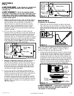
1a. From where you have access to inside the fan’s junction box, connect
the one white wire from the house to both the white wire from the
fan’s light receptacle and the white wire from the fan’s exhaust
receptacle. Connect the first black wire from the wall switch to the
black wire from the fan’s light receptacle. Connect the second black
wire from the switch to the fan’s exhaust receptacle. Connect
the ground wire from the house to the green wire from the fan’s
receptacle
(Figure 7).
Use approved methods for all connections.
2.
Wiring Fan/Light together:
Run wiring from an approved wall switch
carrying the appropriate rating. One neutral (white), one ground (green
or bare copper), and one hot (black lead connected to the switch).
Secure the electrical wires to the housing with an approved electrical
connector. Make sure you leave enough wiring in the box to make the
connection to the fan’s receptacle.
2a. From where you have access to inside the fan’s junction box, connect
the one white wire from the house to both the white wire from the
fan’s light receptacle and the white wire from the fan’s exhaust
receptacle. Connect the black wire from the wall switch to both the
black wire from the fan’s light receptacle and the black wire from the
fan’s exhaust receptacle. Connect the ground wire from the house to
the green wire from the fan’s receptacle
(Figure 8).
Use approved
methods for all connections.
www.airkinglimited.com
A210572219 Rev. D 12-12
3 of 12
SECTION 6
Completing the Installation
1. Reinstall the fan’s wire compartment cover. Rotate the blower wheel
by hand to ensure it spins freely. Plug the fan’s quick connect motor
cord into the receptacle. This cord will only fit one way into the
receptacle
(Figure 9).
NOTE:
If using this fan to meet ASHRAE 62.2 requirements, locate the label
inside the fan housing and fill in the appropriate information.
2. Install the grill/lens/light reflector, by first removing the lens from the
grill (there are two tabs on either side that hold the lens in place).
Then remove the acorn nut and the lock washer which are installed
on the reflector mounting bolt in the fan housing. Adjust the height
of the reflector mounting bolt so that the grill will be tight up against
the finished ceiling and less than 1/4” of the reflector mounting bolt
protrudes through the reflector. Secure the reflector bolt’s position by
tightening the factory installed nut against the motor clip
(Figure 10).
CAUTION:
FAILURE TO SECURE THE REFLECTOR BOLT MAY
RESULT IN A RATTLING OR HUMMING NOISE.
3. After the reflector bolt is secure, raise the grill/reflector up into position
and plug the reflector into the appropriate receptacle. Secure the
assembly to the reflector bolt using the acorn nut and lock washer.
Install the included 26 watt fluorescent lamp into the lamp holder by
lining up the pins on the lamp base to the socket of the lamp holder and
turning the lamp body clockwise until the lamp snaps into place and is
firmly seated in the lamp holder
(Figure 11).
Figure 9
Motor Clip
Mounting Bolt
Reflector
Grill
Lens
Tabs
Flange Nut
Figure 10
Nut
Supply
from
house
Ground
(Green or
Bare)
Neutral (White)
Figure 8
Hot (Black)
Hot (Black)
Supply
from
house
Ground
(Green or
Bare)
Neutral
(White)
Figure 7
Hot (Black)
Hot (Black)


