2b.
TWO SPEED UNITS
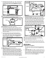
(models ES80DG and ES130DG): Plug the fan’s 2
pin and 3 pin quick connect motor cords into the receptacles located
on the side of the wire compartment. Plug the 3 pin quick connect
cord from the motion sensor on the grill into the receptacle coming out
of the top of the wire compartment. These cords will only fit one way
into the receptacles
(Figure 12).
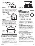
3. Install the ceiling mounting flange to cover any gaps which exist
between the housing and the finished ceiling. Remove the two screws
that connect the ceiling mounting flange to the housing. Put caulk (not
provided) on each corner of the ceiling mounting flange to ensure that
the flange fits tightly against the ceiling. Line up the screw holes in the
ceiling mounting flange with the screw holes on the inside of the housing
and press flange in place so it is tight against the ceiling. Reinstall ceiling
flange mounting screws inside the housing
(Figure 13)
.
NOTE:
If the housing is mounted to far or not far enough into the ceiling for
the flange to make a solid connection, loosen the mounting channel and
adjust the housing up or down on the rails. Once in place, fully tighten the
mounting channel nuts.
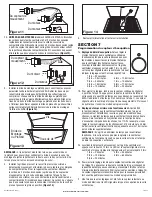
4. Install the grill by squeezing the spring furthest from the motion
sensor together and installing it up into the slot furthest from the wire
compartment on the fan’s housing. Attach the 3 pin quick connect
from the motion sensor on the grill to either the harness installed in
Step 2a
(Single Speed Models) or the connector from the top of the
wire compartment (Two Speed Models). This cord will only fit one way
into the receptacle. Install the other spring in place and push the grill
up into position
(Figure 14).
www.airkinglimited.com
A210572215 Rev. D 8-12
4 of 12
5. Restore power and test your installation.
SECTION 7
Programming the Occupancy Sensor
1a.
Setting the Occupancy Time Delay.
This will set
the amount of time the fan will continue to operate
after the room is vacated or on dual speed models
the amount of time the fan will run on high speed.
Locate the motion sensor on the fan’s grill and
press the button 2 times. The LED on the sensor
will then flash the number of times to indicate the
current setting, this will repeat 3 times:
1 time = 30 seconds
2 times = 2.5 minutes
6 times = 12.5 minutes
3 times = 5 minutes
7 times = 15 minutes
4 times = 7.5 minutes
8 times = 17.5 minutes
5 times = 10 minutes
9 times = 20 minutes
1b. To adjust the setting, while the sensor is still flashing from
Step 1a
,
press the button the number of times that corresponds with the
amount of time you desire, for instance 3 times sets the delay to
5 minutes (see numbers in
Step 1
). The sensor will then flash the
number of times for the new setting 3 times before exiting back to the
programming mode.
2a
Setting the Minimum On Time.
This sets the minimum time the fan
will operate once motion is detected within the room or on dual speed
models the amount of time the fan will run on high speed. This works
in conjunction with the Occupancy Time Delay feature set in
Steps 1a
and
1b
. For instance if you set the minimum time on for 15 minutes
and the Time Delay for 5 minutes, the fan will operate for at least 15
minutes then 5 additional minutes.
NOTE:
This is a minimum time that the fan will operate. If the room is
occupied longer, the fan will continue to run until the room is vacated
and the occupancy time delay has elapsed.
2b. Locate the motion sensor on the fan’s grill and press the button 10
times. The LED on the sensor will then flash the number of times to
indicate the current setting, this will repeat 3 times:
1 time = 0 minutes
4 times = 45 minutes
2 times = 15 minutes
5 times = 60 minutes
3 times = 30 minutes
2c. To adjust the setting, while the sensor is still flashing from
Step 2b
,
press the button the number of times that corresponds with the
amount of time you desire, for instance 3 times sets the minimum on
time to 30 minutes (see numbers in
Step 2b
). The sensor will then flash
the number of times for the new setting 3 times before exiting back to
the programming mode.
3. Once all setting have been made and the sensor will return to detection
mode and the LED will flash when occupancy of the room is detected.
Figure 12
Figure 13
Screws
Ceiling
Mounting
Flange
Screw Holes
Figure 14
Figure 11
From
Motor
From
Sensor
From
Motor
From Motor
From
Sensor
From Motor


