background image

1b.  Internal Wire Compartment: Using a 7/16" socket, remove the two hex nuts 

holding the blower assembly in place. Lift up on the assembly and slide it 

out of the tabs on the housing 

(Figure 6).

 Remove the wire compartment 

cover screw and place the cover in a secure place 

(Figure 7).

NOTE:

 If the fan motor plug is connected to the fan housing receptacle, 

unplug so the blower assembly can be completely removed.

SINGLE SPEED UNITS

 (models ES80SH and ES130SH)

2a.  For proper operation the humidity sensing fan will require a 3 way 

switch (not included).  Run wiring between the fan and the switch 

location. Make sure you leave enough wiring in each box to make the 

connections. At the switch box connect the black wire from the house 

to the common terminal of the switch. Connect the black wire from 

the fan to one of the switched terminals on the switch. This position 

will energize the automatic mode and the fan will energize upon a rise 

in humidity. Connect the red wire from the fan to the other switched 

terminal on the switch. This position will activate the Manual On 

feature and energize the fan.  Properly connect the ground and neutral 

(if applicable) mount the switch and the cover.

2b.  From where you have chosen to access the fan’s junction box, connect 

the white wire from the house to the white wire from the fan. Connect 

the wire from the automatic position on the wall switch to the black 

wire from the fan, connect the wire from the manual On position on 

the switch to the red wire from the fan. Connect the ground wire from 

the house to the green wire from the fan housing 

(Figure 8).

 Use 

approved methods for all connections.

TWO SPEED UNITS

 (models ES80DH and ES130DH)

3. 

Continuous Ventilation:

 For two speed fans wired for continuous 

ventilation, connect the White wire of the fan to the White (Neutral) 

wire from the power source. Connect the ground wire from the house

www.airkinglimited.com

6728020 Rev. B 8-12

3 of 12


to the green wire from the fan housing. Connect the Black wire of the 
fan to the Black wire (Hot) from the power source. The fan will operate 
on low speed continuously and boost to high upon a rise in humidity. 
A manual override switch (not included) can be used to provide a 
manual fan Off function. 

(Figure 9).

NOTE:

 The fan’s receptacle wires might need to be pulled outside 

compartment for connection. Only pull the five loose wires outside of 
compartment. Additional wires will be present.

NOTE:

 Unit must be grounded according to all local and national codes.

4.  Carefully tuck wire back inside wire compartment and replace wire 

compartment cover securing with the screw that was removed earlier.

SECTION 6

Completing the Installation

1.  If the fan’s blower assembly was removed during the wiring process, 

reinstall the blower by reversing the directions in 

Section 4

 (Wiring), 

Step 1b.

2.  Plug the fan’s 3 pin quick connect motor cord into the receptacle 

located on the side of the wire compartment cover. Plug the 2 pin 
quick connect motor cord into the receptacle from the capacitor on 
single speed models (ES80SH, ES130SH), or on the side of the wire 
compartment on dual speed models (ES80DH, ES130DH). These cords 
will only fit one way into the receptacles 

(Figure 10).

3.  Install the ceiling mounting flange to cover any gaps which exist 

between the housing and the finished ceiling. Remove the two screws 
that connect the ceiling mounting flange to the housing. Put caulk (not 
provided) on each corner of the ceiling mounting flange to ensure that 
the flange fits tightly against the ceiling. Line up the screw holes in the

Plug

Tabs

Hex Nuts

Figure 6

Figure 7

Screw

Wire Compartment 

Cover

Humidity Set 

Point Knob

NOTE:

 Wire compartment configuration will be dependent on model.

Figure 9

Supply from house

Ground

White

Hot (Black)

Figure 8

Supply from house

Ground

White

Hot (Black)

Red

Figure 10

SINGLE SPEED UNITS

DUAL SPEED UNITS

Summary of Contents for ES130DH

Page 1: ...must be done by qualified person s in accordance with all applicable codes and standards including fire related construction b Sufficient air is needed for proper combustion and exhausting of gases through the flue chimney of fuel burning equipment to prevent back drafting Follow the heating equipment manufacturer s guideline and safety standards such as those published by the National Fire Protec...

Page 2: ...eiling material Figure 3 Set housing aside and cut opening being careful not to cut or damage any electrical or other hidden utilities Install the rails into the mounting channel on the housing Center the mounting channel in the slots on the housing then from inside the housing tighten the mounting channel nuts so the channel is securely in place Position the housing in the previously cut hole so ...

Page 3: ...power source Connect the ground wire from the house www airkinglimited com 6728020 Rev B 8 12 3 of 12 to the green wire from the fan housing Connect the Black wire of the fan to the Black wire Hot from the power source The fan will operate on low speed continuously and boost to high upon a rise in humidity A manual override switch not included can be used to provide a manual fan Off function Figur...

Page 4: ...ses higher than the preset level the fan will turn on even if the room is not occupied This helps prevent conditions that lead to mold growth CAUTION MAKE SURE POWER IS SWITCHED OFF AT SERVICE PANEL BEFORE SERVICING THE UNIT 1 To set the desired humidity level of the room remove the grill and locate the dehumidistat dial located on the wire compartment cover 2 Set the dial to the relative humidity...

Page 5: ... unauthorized repairs made or attempted This warranty does not cover shipping costs for the return of products to Air King for repair or replacement Air King will pay return shipping charges from Air King following warranty repairs or replacement ANY AND ALL WARRANTIES EXPRESSED OR IMPLIED INCLUDING WITHOUT LIMITATION ANY IMPLIED WARRANTY OF MERCHANTABILITY LAST ONE YEAR FROM THE DATE OF ORIGINAL ...

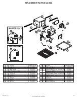
Page 6: ...sher 5S1112012 12 2 Grommets 5S1202032 Qty Description Replacement Part 13 1 10 Ground Screw 5S1999002 14 1 14 ga Ground Wire 5S1999003 15 1 Wire Compartment Assembly ES80S ES130S 5S1299801 16 1 Wire Harness ES80S 5S2239002 Wire Harness ES130S 5S2239003 17 1 Wire Compartment Assembly ES80D ES130D 5S1299803 18 2 Wire Cover Screw 6 5S1999010 19 1 Knob 5S1299802 20 2 Flange Screw 5S1202049 21 1 Ceili...

Page 7: ... conformité avec tous les codes et normes applicables incluant la construction relative aux incendies b De l air en quantité suffisante est requis pour la bonne combustion et l évacuation de gaz par le conduit cheminée provenant d équipement de brûlage au combustible pour prévenir un refoulement Suivre les directives du fabricant de l équipement de chauffage et les normes de sécurité telles que ce...

Page 8: ...tention de ne pas couper ou endommager les installations électriques ou d autres utilités masquées Installez les rails dans le canal de montage sur le boîtier Centrez le canal de montage dans les fentes sur le boîtier puis de l intérieur du boîtier serrez les écrous de montage de sorte que le canal soit bien en place Positionnez le boîtier dans le trou préalablement découpé de sorte qu il soit ali...

Page 9: ...on continue Pour les ventilateurs à deux vitesses câblés pour la ventilation continue connectez le fil blanc du ventilateur au fil neutre blanc de la source d alimentation Connectez le fil de terre de la maison au fil vert du boîtier du ventilateur Connectez le fil noir du ventilateur au fil noir chaud de la source d alimentation Le ventilateur fonctionnera à vitesse réduite continuellement et aug...

Page 10: ...onsigne du capteur d humidité Dans le cas où le niveau d humidité ambiante de la pièce s élève plus haut que le niveau préréglé le ventilateur s allumera même si la salle n est pas occupée Ceci aide à éviter les conditions qui mènent à la croissance de moisissures AVERTISSEMENT VOUS ASSURER QUE L ALIMENTATION EST COUPÉE AU PANNEAU DE SERVICE AVANT DE COMMENCER L INSTALLATION 1 Pour régler le nivea...

Page 11: ...se manipulation ou opération de dommages d expédition d abus de mauvaise utilisation de réparation faite ou tentées non autorisées Cette garantie ne couvre pas les coûts d expédition pour le retour des produits à Air King pour la réparation ou le remplacement Air King payera les frais d expédition de retour de Air King après les réparations ou le remplacement de garantie TOUTES LES GARANTIES EXPRE...

Page 12: ...2 2 Passe fil 5S1202032 Qty Description Replacement Part 13 1 Vis 10 de mise à la terre 5S1999002 14 1 Fil de mise à la terre de calibre 14 5S1999003 15 1 Assemblée du compartiment du fil ES80S ES130D 5S1299801 16 1 Faisceau électrique ES80S ES130S 5S2239002 Faisceau électrique ES80S ES130S 5S2239003 17 1 Assemblée du compartiment du fil ES80D ES130D 5S1299803 18 2 Vis 6 de la couverture du fil 5S...

Reviews: