6
MN-870
Air Lift Performance
5. Route the braided air line in a manner where the line will not be kinked or rubbed by
anything. Cycle the suspension up and down and turn the wheel lock-to-lock to verify
the air line is protected from damage. Generally, routing the air line along with the brake
line is a good place to start.
6. With the suspension fully compressed, take a measurement from the fender to some
reference point, typically the center of the axle. Record this as Max Compression (MC).
Cycle the suspension to Max Extension (ME) and record the measurement from the
same reference points. Take the difference between the two numbers and divide by
two. Add that value to the Max Compression number and then set the suspension to
that point (fig. 6). This position gives 50% stroke in either direction and is a great starting
point for ride height. At this position torque the lower control arm bolts to manufacturer’s
specifications (Table 1).
Formula for calculating ride height:
7. Reinstall wheels; retake the Max Compression and Extension measurements from the
fender to lower wheel lip. Recalculate the ride height at 50% stroke and set the vehicle
to that height. Make sure to get an alignment at the preferred drive height. Enjoy the new
look and handling!
ALIGNING THE VEHICLE
1. Using the control system, set the vehicle height to the new custom ride height.
2. If the custom ride height is lower than stock, we recommend loosening all pivot points
(bolts, nuts) on any control arm, strut arm or radius rod that contains bushings. Once
they have been loosened, re-torque to stock specifications.
It may be necessary to cycle the suspension to loosen the bushing up from its mount. This
will help unload the bushing to make it last longer at its new position based on the custom
ride height.
DAMPING ADJUSTMENT
The struts in this kit have 30 settings or “clicks” of adjustable compression and rebound
damping characteristics. Damping is changed through the adjuster at the top of the strut.
Turn the adjuster clockwise and the damping settings are hardened. Turn the adjuster
counterclockwise and the damping is softened. Each front strut is preset to “-15 clicks”. This
means that the strut is adjusted 15 clicks away from full stiff. Counting down from full stiff
is the preferred method of keeping track/setting of damping. (Figs. 7, 8)
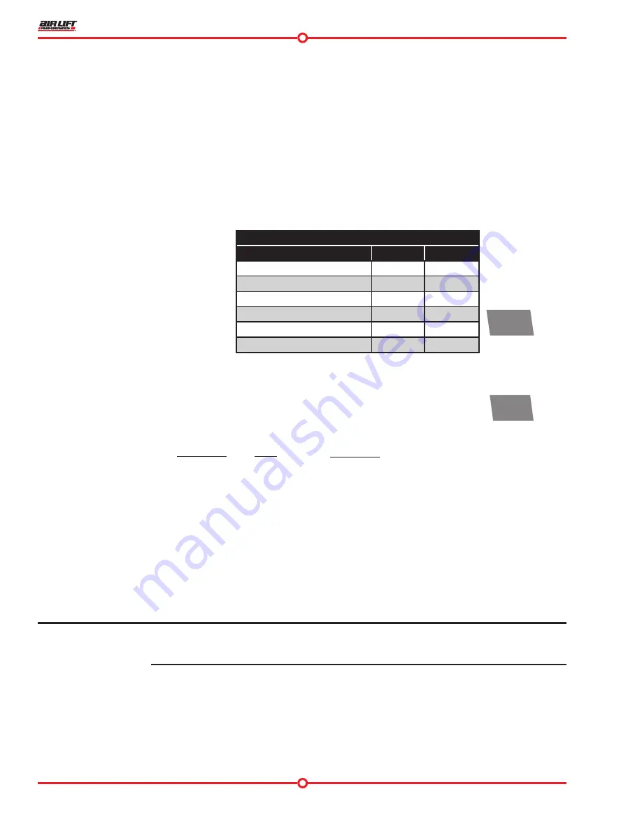
Table 1
Torque Specifications
Location
Nm
Lb-ft
Camber plate to chassis
20
15
Camber plate adjustment bolts
15
11
Strut lower mount bolts
175
129
Brake hose bolt
32
24
Stabilizer bar to transverse link
30
22
Wheel bolts
120
89
fig. 6
ME
- MC
X
X = Y
2
Step 1:
+ MC
Z
Y
Z = DESIGN HEIGHT
Step 3:
Answer:
Step 2:
NOTE


