background image

8

MN-282

5.  Push the inflation valve through the hole and use the rubber washer, flat washer, and 

another 5/16” nut. Tighten the nuts to secure the assembly in place (fig. 8).

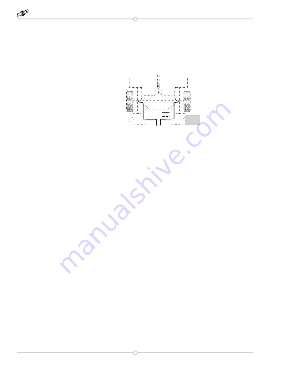
6.  Route the air line along the frame to the air fitting on the air spring (fig. 9). Keep AT 

LEAST 6” of clearance between the air line and heat sources, such as the exhaust pipes, 

muffler, or catalytic converter. Avoid sharp bends and edges. Use the plastic tie straps 

(BB) to secure the air line to fixed, non-moving points along the chassis. Be sure that 

the tie straps are tight, but do not pinch the air line. Leave at least 2” of slack to allow for 

any movement that might pull on the air line.

7.


Cut off air line leaving approximately 12” of extra air line. A clean square cut will ensure 

against leaks (see fig. 7). Insert the air line into the air fitting. This is a push to connect 

fitting. Simply push the air line into the 90° swivel fitting until it bottoms out (9/16” of air 

line should be in the fitting).

ALIGNING THE AIR SPRING

1.

  VERY IMPORTANT

  -  With  the  top  and  bottom  still  loose,  inflate  the  air  springs  to 

approximately  10  p.s.i.  Use  the  slots  in  the  brackets  to  correctly  align  the  air  spring 

between the upper and lower brackets. This can be accomplished by tapping it inboard 

or outboard for proper alignment. There should be symmetrical cushion of air around 
the base of the air spring when correctly positioned.

CHECKING FOR LEAKS

1.  Inflate the air spring to 30 p.s.i. and spray all connections and the inflation valves with 

a solution of 1/5 liquid dish soap and 4/5 water to check for leaks. Spot leaks easily by 

looking for bubbles in the soapy water.

2.  After the test, deflate the springs to the minimum pressure required to restore the normal 

ride height, no less than 5 p.s.i.

3.


Check the air pressure again after 24 hours. A 2-4 p.s.i. loss after initial installation is 

normal. Retest for leaks if the loss is more than 5 lbs.

FIXING LEAKS

1.  If there is a problem with the swivel fitting:

a.  Check the air line connection by deflating the spring and removing the line by pulling 

the collar against the fitting and pulling firmly on the air line. Trim 1” off the end of 

the air line. Be sure the cut is clean and square (see fig. 7). Reinsert the air line into 

the push-to-connect fitting.

b.  Check the threaded connection by tightening the swivel fitting another ½ turn. If it still 

leaks, deflate the air spring, remove the fitting, and re-coat the threads with thread 

sealant. Reinstall by hand tightening as much as possible, then use a wrench for an 

additional two turns.

2.  If there is a problem with the inflation valve, then:

a. 

Check the valve core by tightening it with a valve core tool.

b.  Check the air line connection by removing the air line from the barbed type fitting. 

Option 1
Option 2

fig. 9

RideControl

Summary of Contents for Ride Control 59516

Page 1: ...eness and safety please read these instructions completely before proceeding with installation Failure to read these instructions can result in an incorrect installation MN 282 121305 ECR 7644 INSTALLATION GUIDE Kit 59516 ...

Page 2: ...t 5 Assembling the Installation Tool 5 Installing the RideControl System 5 Attaching the Assembly 5 Installing the Air Lines 7 Aligning the Air Spring 8 Checking for Leaks 8 Fixing Leaks 8 Maintenance and Servicing 9 Minimum and Maximum Pressure 9 Maintenance Guidelines 9 Warranty and Return Policy 9 Replacement Information 10 Contact Information 10 TABLE OF CONTENTS 1 ...

Page 3: ...e Check your vehicle s owner s manual and do not exceed the maximum load listed for your vehicle Gross Vehicle Weight Rating The maximum allowable weight of the fully loaded vehicle including passengers and cargo This number along with other weight limits as well as tire rim size and inflation pressure data is shown on the vehicle s Safety Compliance Certification Label Payload The combined maximu...

Page 4: ...lon nut Star washer 3 8 16 X 1 5 Frame bolt Upper bracket Lower bracket Air sleeve 3 8 16 Lock nut 3 8 Flat washer Flat washer 3 8 16 Lock nut HHCS bolt Flat washer 3 8 U bolt NOTE The lower bracket must be installed with the flat edge inboard Spacer optional RideControl ...

Page 5: ...sing or damaged parts Call Air Lift customer service at 800 248 0892 for a replacement part Getting Started IMPORTANT NOTES 1 Your vehicle may be equipped with a rear brake proportioning valve Any type of load assist suspension product could effect brake performance We recommend that you check with your dealer before installing this type of product If your vehicle does not have a proportioning val...

Page 6: ...in the correct mounted height is determined by the upper threaded section of the tool The kit may be mounted anywhere in that range fig 3 2 Place the upper bracket legs down onto the threaded end of the tool resting on the bottom nylon nut Then thread a second nylon nut onto the tool to hold the bracket in place Leave loose for later adjustment fig 3 3 Use the x 7 8 hex head bolt and flat washer t...

Page 7: ...ELECTRICAL WIRES HAVE BEEN MOVED ASIDE ON BOTH SIDES OF FRAME RAIL 4 Using the upper bracket as a template centerpunch one of the lower mounting holes and drill a 3 8 hole through the frame Install one of the mounting bolts and LOOSELY attach the oversized flat washer and locknut Now centerpunch and drill a 3 8 hole at the other lower mounting hole location DO NOT insert the mounting bolt at this ...

Page 8: ...r the gas cap access door d Through license plate itself What ever the chosen location is make sure there is enough clearance around the inflation valves for an air chuck 2 Drill a 5 16 hole to install the inflation valves 3 Cut the air line assembly in two equal lengths WHEN CUTTING OR TRIMMING THE AIR LINE USE A HOSE CUTTER A RAZOR BLADE OR A SHARP KNIFE A CLEAN SQUARE CUT WILL ENSURE AGAINST LE...

Page 9: ...uld be symmetrical cushion of air around the base of the air spring when correctly positioned CHECKING FOR LEAKS 1 Inflate the air spring to 30 p s i and spray all connections and the inflation valves with a solution of 1 5 liquid dish soap and 4 5 water to check for leaks Spot leaks easily by looking for bubbles in the soapy water 2 After the test deflate the springs to the minimum pressure requi...

Page 10: ...ir to the springs in small quantities checking the pressure frequently Sleeves require less air volume than a tire and inflate quickly 6 Should it become necessary to raise the vehicle by the frame make sure the system is at a minimum pressure 5 p s i to reduce tension on the suspension brake components Use of on board leveling systems do not require deflation or disconnection NOTE CAUTION Mainten...

Page 11: ...tion RMA number Returns to Air Lift can be sent to Air Lift Company 2727 Snow Road Lansing MI 48917 Product failures resulting from abnormal use or misuse are excluded from this warranty The loss of use of the product loss of time inconvenience commercial loss or consequential damages is not covered The consumer is responsible for installation reinstallation labor charges of the product Air Lift C...

Page 12: ...airliftcompany com Thank you for purchasing Air Lift products the professional installer s choice Printed in the USA Need Help Contact our customer service department by calling 800 248 0892 Monday through Friday For calls from outside the USA or Canada our local number is 517 322 2144 Register your warranty online at www airliftcompany com warranty ...

Reviews: