background image

6

MN-751

WirelessONE

RECOMMENDED COMPRESSOR LOCATIONS 

Important


LOCATE COMPRESSOR IN DRY, PROTECTED AREA ON VEHICLE. 

DIRECT SPLASH OR EXCESSIVE MOISTURE CAN DAMAGE 

THE COMPRESSOR AND CAUSE SYSTEM FAILURE.

Disclaimer: If you choose to mount the compressor outside the vehicle please keep in mind 
the compressor body must be shielded from direct splash.

Please also remember . . .

•  To avoid high heat environments. 

•  To avoid mounting the compressor under the hood.

•  To check to be sure the compressor harness #2 will reach the compressor and 

connect to harness #1.

•  The compressor can be mounted in any position — vertical, upside down, sideways, 

etc. (Please refer to the instruction manual).

INSTALLING THE COMPRESSOR

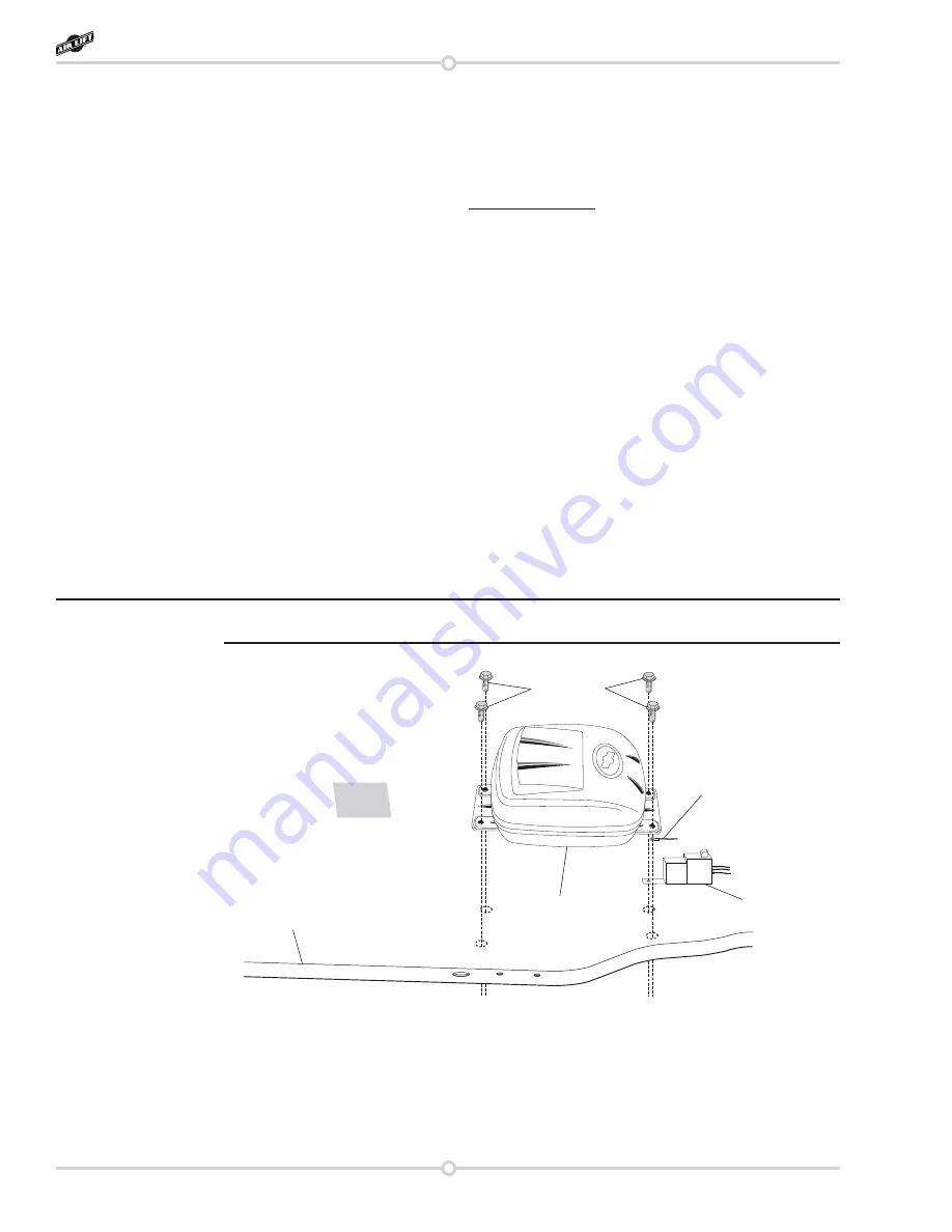
1.  Select a rigid mounting location for the compressor on the vehicles frame or crossmember 

(fig. 3) that shields the compressor from the elements and heat sources.

The electrical harness will force the compressor to be within 24” of the manifold in order to 
make electrical connections.

2.  Use the supplied self tapping fasteners to fasten the compressor to the frame or cross 

member.

•  One of the self tapping screws will be used as an electrical ground for the 

compressor ring terminal.

•  Another of the self tapping screws can be used to mount the compressor relay.

Compressor

Frame

Relay

Compressor Ground

Self-tapping

Screws

fig. 3

Installing the WirelessONE System

NOTE

Summary of Contents for Wireles One 25870

Page 1: ...ness and safety please read these instructions completely before proceeding with installation Failure to read these instructions can result in an incorrect installation INSTALLATION GUIDE Kit 25870 Key Fob Activated Compressor System WirelessONE ...

Page 2: ......

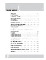
Page 3: ...e Manifold 7 Installing the Harness 7 Attaching the Air Lines 8 How to Remove and Install the Batteries in the Remote Contrtol Unit 9 Operational Modes 10 Normal Mode 10 Settings Mode 10 Saving and Recalling Memory 1 11 Saving and Recalling Memory 2 11 Saving and Recalling Memory 3 11 How to Sync the Receiver to the Transmitter 12 Checking the System 12 FCC Information to User 12 Warranty and Retu...

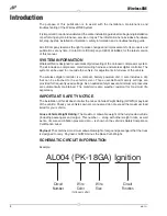
Page 4: ...ess digital controller is a compact battery powered unit It also includes a clip that can be attached to the vehicle s visor Three user defined memory settings are provided for frequently used settings As an added safety measure minimum air pressures are automatically maintained The manifold is also weather resistant for maximum life expectancy IMPORTANT SAFETY NOTICE The installation of this kit ...

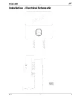
Page 5: ...3 MN 751 WirelessONE Installation Electrical Schematic fig 1 ...

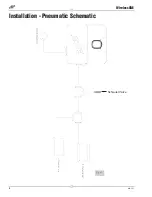
Page 6: ...4 MN 751 WirelessONE Installation Pneumatic Schematic fig 2 Schrader Valve ...

Page 7: ...04 Key Fob 1 B 72701 Wireless manifold 1 C 16060 Compressor 1 D 20946 20 ft hose 1 4 1 E 26514 Wireless manifold harness 1 Hardware Pack F 21838 Tee 1 4 PTC 2 G 24652 ATC fuse spade 15A 1 H 24561 Adapter mini fuse 1 I 24542 1 4 ATC ATO tap in fuse 1 J 24595 Female spade 12 ga 1 Item Part Description Qty K 24524 3 16 female spade 1 L 24661 Heat shrink butt splice 14 16 ga 1 M 24752 Heat shrink butt...

Page 8: ...in any position vertical upside down sideways etc Please refer to the instruction manual INSTALLING THE COMPRESSOR 1 Select a rigid mounting location for the compressor on the vehicles frame or crossmember fig 3 that shields the compressor from the elements and heat sources The electrical harness will force the compressor to be within 24 of the manifold in order to make electrical connections 2 Us...

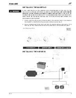
Page 9: ...COMMENDED THAT THIS PRODUCT S MSDS SHEET BE REVIEWED BEFORE USE THIS CAN BE OBTAINED WHERE YOU PURCHASED THIS PRODUCT 1 Select a rigid mounting location for the manifold on the vehicles frame or crossmember that shields the manifold from the elements and heat sources fig 4 2 Use mounting bracket 11027 R to secure to the rigid mounting surface with a 17173 fastener S The manifold should not be the ...

Page 10: ... not needed b Strip off 1 4 insulation off both sides of the inline fuse holder N and the AL004 RD 10GA wire c Crimp on the weather proof yellow butt splice M to AL004 RD 10GA wire d Crimp on the weather proof yellow butt splice M to one side of the inline fuse holder O Heat butt splice to seal connection e Select the appropriate type of fuse tap in terminal for your application fig 6 f Crimp on t...

Page 11: ...CONTROL UNIT 1 To remove the two CR2032 batteries use a small flat screw driver to seperate the two halves of the key fob by prying at the internal clip locations shown in figure 7 2 Stack the two CR2032 batteries Positive to Negative inside the rear cover 3 Clip the front cover and circuit board into the rear cover fig 8 Internal Clips Internal Clips fig 7 M2 M1 The case must be aligned as shown ...

Page 12: ...y 1PSI or 0 1BAR depending on the unit of measure selected When the user releases the button the new desired pressure will be transmitted to the receiver 4 Holding the up arrow will increment the desired pressure in units of 5PSI or 0 5BAR depending on the unit of measure selected When the user releases the button the new desired pressure will be transmitted to the receiver 5 The Maximum pressure ...

Page 13: ...button to set the M2 pressure as the desired pressure Upon the press of the M2 button the display will display M2 Once the button is released the display will display the new desired pressure and transmit the desired pressure to the receiver Saving to Memory Press and hold the memory button for 5 seconds to set the desired pressure to memory 2 While the M2 button is pressed the display will displa...

Page 14: ...he yellow wire terminal into the molded cap CHECKING THE SYSTEM 1 Pressurize the system to check for leaks 2 Inspect all air line connections with a solution of 1 5 dish soap to 4 5 water If a leak is detected in a push lock fitting cut the hose end square and reinstall the air line to the fitting Make sure the air line is cut off squarely and that the air line is completely pushed into the fittin...

Page 15: ...rranty The loss of use of the product loss of time inconvenience commercial loss or consequential damages is not covered The consumer is responsible for installation reinstallation labor charges of the product Air Lift Company reserves the right to change the design of any product without assuming any obligation to modify any product previously manufactured This warranty gives you specific legal r...

Page 16: ... where the kit was purchased If it is necessary to return or exchange the kit for any reason If there is a problem with shipping if shipped from the retailer If there is a problem with the price Contact Information If you have any questions comments or need technical assistance contact our customer service department by calling 800 248 0892 Monday through Friday For calls from outside the USA or C...

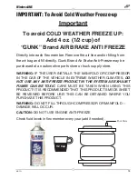
Page 17: ...pply store WARNING IF THE USER INSTALLS THE MANIFOLD OR COMPRESSOR IN THE CAB OF THE VEHICLE IN EXTREME WEATHER CLIMATES DO NOT USE ANY ANTI FREEZE PRODUCT IN THE SYSTEM AS EXHAUST FUMES CAN BE TOXIC CARE MUST BE TAKEN WHEN USING THIS PRODUCT IT IS RECOMMENDED THAT THIS PRODUCT S MSDS SHEET BE REVIEWED BEFORE USE THIS CAN BE OBTAINED WHERE YOU PURCHASE THIS PRODUCT WARNING DO NOT FILL THROUGH COMP...

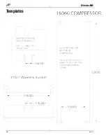
Page 18: ...16 MN 751 WirelessONE Templates ...

Page 19: ...17 MN 751 WirelessONE Notes ...

Page 20: ...airliftcompany com Thank you for purchasing Air Lift products the professional installer s choice Printed in the USA Need Help Contact our customer service department by calling 800 248 0892 Monday through Friday For calls from outside the USA or Canada our local number is 517 322 2144 Register your warranty online at www airliftcompany com warranty ...

Reviews: