background image

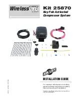
WirelessONE

TOOLS LIST

Description  . . . . . . . . . . . . . . . . . . . . . . . . . . . . . . . . . . . . . . . . . . . . . . Qty

Hoist or floor jacks

 ................................................ 1

Safety stands ........................................................

2

Safety glasses ...................................................... 1
Heavy duty drill ..................................................... 1

#2 Phillips bit driver

 .............................................. 1 

Description  . . . . . . . . . . . . . . . . . . . . . . . . . . . . . . . . . . . . . . . . . . . . . . Qty 

7/32 & 1/4 Drill bits

 ............................................... 1

5/16 Driver

 ............................................................ 1

Hose cutter ........................................................... 1
Spray bottle with dish soap/water solution ........... 1

Digital volt meter

 ................................................... 1

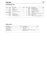
HARDWARE LIST

 Item  Part # 

Description . . . . . . . . . . . . . . . . . . . . . . . . . . . . . . . .Qty


72704 

Key Fob

 ...............................................1

  B 

72701 

Wireless manifold

 ................................1

   C 

16060 

Compressor

 ........................................1

  D 

20946 

20 ft. hose (1/4”)

..................................1


26514 

Wireless manifold harness

 ..................1

Hardware Pack
 

  F 

21838 

Tee 1/4 PTC 

 .......................................

2

   G 

24652 

ATC fuse, spade 15A

 ..........................1

   H 

24561 

Adapter mini fuse

 ................................1

  I 

24542 

1/4 ATC/ATO tap in fuse

 .....................1


Item 

Part  # 

Description . . . . . . . . . . . . . . . . . . . . . . . . . . . . . . . .Qty  

  J 

24595 

Female spade, 12 ga

 ..........................1

   K 

24524 

3/16” female spade

 .............................1

  L 

24661 

Heat shrink butt 16 ga

 .........................1


  M 

24752 

Heat shrink butt 12-10 ga

....................1

  N 

24539 

Fuse holder ATC/ATO

 ........................1

  O 

10466 

8” Zip Tie

 .............................................5

  P 

17428 

10-24 x 3/8” Slot Hex Head Screw

......

2

  Q 

72704-012 CR2032 Battery

 ..................................

2

  R 

11068 

Bracket

 ................................................1

  S 

17173 

#14-1/4”x3/4” Self Tapping Screws

.....

2

Summary of Contents for WirelessONE 25870

Page 1: ...ess and safety please read these instructions completely before proceeding with installation Failure to read these instructions can result in an incorrect installation INSTALLATION GUIDE Kit 25870 Key...

Page 2: ...to the vehicle s visor Three user defined memory settings are provided for frequently used settings As an added safety measure minimum air pressures are automatically maintained The manifold is also w...

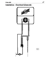
Page 3: ...WirelessONE Installation Electrical Schematic fig 1...

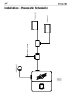
Page 4: ...WirelessONE Installation Pneumatic Schematic fig 2 Schrader Valve...

Page 5: ...ifold 1 C 16060 Compressor 1 D 20946 20 ft hose 1 4 1 E 26514 Wireless manifold harness 1 Hardware Pack F 21838 Tee 1 4 PTC 2 G 24652 ATC fuse spade 15A 1 H 24561 Adapter mini fuse 1 I 24542 1 4 ATC A...

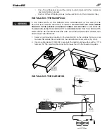
Page 6: ...void high heat environments To avoid mounting the compressor under the hood To check to be sure the compressor harness 2 will reach the compressor and connect to harness 1 The compressor can be mounte...

Page 7: ...RECOMMENDED THAT THIS PRODUCT S MSDS SHEET BE REVIEWED BEFORE USE THIS CAN BE OBTAINED WHERE YOU PURCHASE THIS PRODUCT 1 Select a rigid mounting location for the manifold B on the vehicles frame or c...

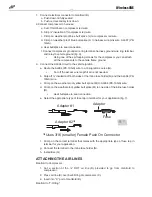
Page 8: ...5A ignition source G Cut off the excess wire length if all is not needed b Strip off insulation off both sides of the inline fuse holder N and the AL004 PK 10GA wire c Crimp on the weather proof yello...

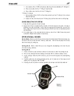
Page 9: ...f the compressor or the solenoid fails to function check the 15 AMP fuse and ground connection Repair and replace as necessary OPERATIONAL MODES Normal Mode Mode in which the user can increment and de...

Page 10: ...nding on the unit of measure selected When the user releases the button the new desired pressure will be transmitted to the receiver 4 Holding the down arrow will decrease the desired pressure in unit...

Page 11: ...n the press of the M1 M2 buttons the display will display M3 Once the buttons are released the display will display the new desired pressure Saving to Memory Press and hold M1 M2 buttons for 5 seconds...

Page 12: ...side the rear cover 3 Clip the front cover and circuit board into the rear cover FCC INFORMATION TO USER THIS DEVICE COMPLIES WITH PART 15 OF THE FCC RULES OPERATION IS SUBJECT TO THE FOLLOWING TWO CO...

Page 13: ...tore WARNING IF THE USER INSTALLS THE MANIFOLD OR COMPRESSOR IN THE CAB OF THE VEHICLE IN EXTREME WEATHER CLIMATES DO NOT USE ANY ANTI FREEZE PRODUCT IN THE SYSTEM AS EXHAUST FUMES CAN BE TOXIC CARE M...

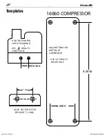
Page 14: ...6300 16060 COMPRESSOR 8 0000 2 0000 USE 1 4 DRILL TO CREATE HOLE HOLE PATTERN FOR BOTTOM OF COMPRESSOR USE 7 32 DRILL TO CREATE HOLE USE 32 DRILL TO CREATE HOLE HOLE PATTERN FOR SIDE OF MANIFOLD 2 100...

Reviews: