5.2
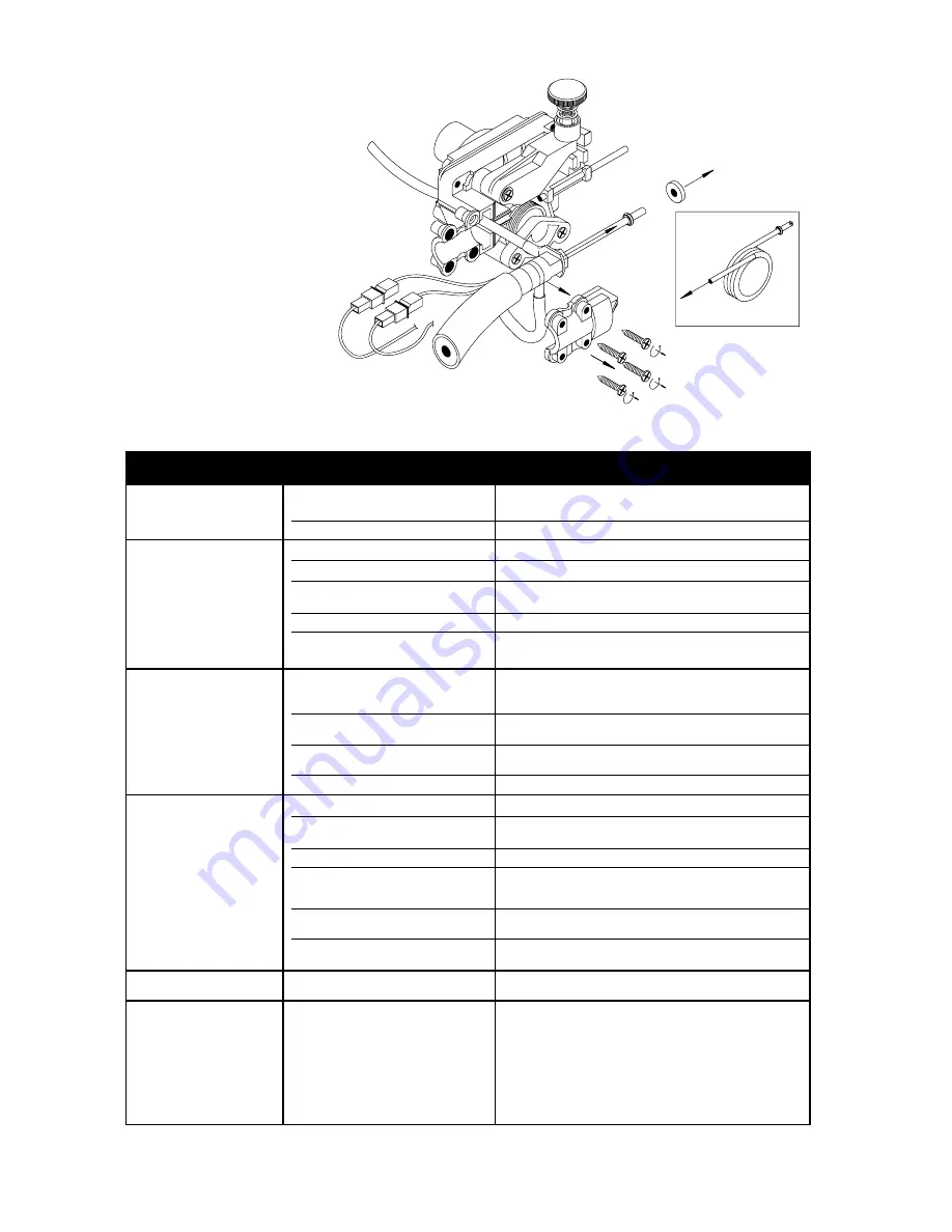
REPLACING THE GUN LINER
1. Turn OFF welder.
2. Follow the instructions in the figure below:
No functions operate
Faulty power cord (one or more
Check and remedy
phases disconnected)
Blown fuse
Replace
Irregular wire feed
Insufficient spring pressure
Tighten pressure assembly knob
Wire-guide blocked
Replace
Wire groove - unsuitable for wire,
Turn roller over or change it
or excessively worn
Excessive braking on coil
Loosen brake using adjusting screw
Oxidized, poorly wound, poor quality wire,
Remedy by removing defective coils. If problem persists,
with tangled or overlapping coils, etc.
change the wire reel
Reduced welding power
Ground cable not connected
Check that the power cord is in good condition and make
sure that the ground clamps are flrmly fixed to the workpiece
Detached or loose connection
Check, tighten or replace, as necessary
on switches
Faulty contactor
Check the state of the contacts and the
mechanical efficiency of the contactor
Faulty rectifier
Visually check for signs of burn-out; if present, replace rectifler
Porous or spongy welds
No gas
Check presence of gas and gas supply pressure
Drafts in the welding area Use a suitable screen. Increase gas delivery
pressure if necessary
Clogged holes in gas diffuser
Clear clogged holes using compressed air
Gas leakage in supply hoses
Check and replace faulty component
Solenoid valve blocked
Check solenoid operation and electrical connection
Faulty regulator
Check operation by removing the hose connecting
the pressure regulator to the power source
Poor quality gas or wire
Gas must be extra-dry; change the cylinder or use
a different type wire
Gas supply does
Worn or dirty solenoid valve
Replace solenoid
not switch off
Presslng torch trigger
Faulty torch trigger, disconnected
Remove the torch connection plug and short circuit the poles;
produces no result
or broken control cables
if the machine operates properly, check the cables and
the torch trigger
Fuse blown
Replace, using a fuse of the same rating
Faulty power switch
Clean with compressed air. Ensure that wires are
tightly secured; replace switch if necessary
Faulty electronic circuit
Replace circuit
TYPE OF BREAKDOWN POSSIBLE CAUSES
CHECKS AND SOLUTIONS
5.3
TROUBLESHOOTING
15
Summary of Contents for M 130
Page 16: ...16 6 M 130 ELECTRICAL DIAGRAM ...
Page 17: ...17 7 M 170 ELECTRICAL DIAGRAM ...
Page 18: ...18 8 M 130 SPARE PARTS LIST ...
Page 19: ...19 CODE ...
Page 20: ...20 9 M 170 SPARE PARTS LIST ...
Page 21: ...21 CODE ...
Page 22: ...22 10 M 130 M 170 COMMON SPARE PARTS LIST CODE CODE ...
Page 23: ...23 11 MG 140 SPARE PARTS LIST ...


