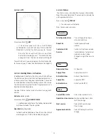
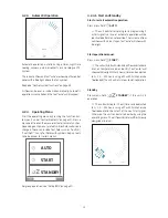
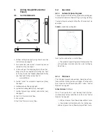
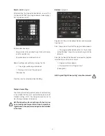
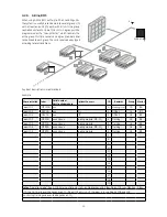
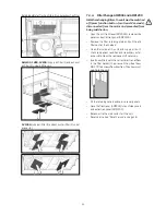
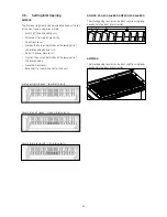
background image

20

N

auto

auto

4.2.6.  Airlinq BMS

When using Airlinq BMS with up to 20 air handling units, 
the system is usually broken down into several groups (G) 
with at least one unit (ID) each, with all units in a group 
controlled uniformly. One of the units in a group will be 
programmed as the “Group Master”, which controls the 
entire group. Multiple sensors and a group control panel 
can be linked to each group. The units can also be equipped 
according to local conditions.

A system description is recommended. 
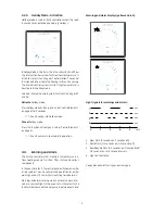
Example:

Airlinq Orbit

Master

ID0

ID1

ID2
ID3
ID3
ID5
ID5

Notes

 "Operation mode": Room 101 timer-control only starts on Wednesday and Friday. Room 102 runs Monday - Friday 

07.00 to 16.00 and override depends on CO

2

. Room 102 only runs if the room is in use. Rooms 104 and 105

runs during training and override depends on CO

2

.

Group

G0

G1

G2
G3
G3
G4
G4

Remarks

Meeting room

Office 1
Office 2
Training
Training
Training
Training

ID

0

1

2
3
4
5
6
7
8
9

10

11

12
13
14
15
16
17
18
19

Options/Sensors

./.
CO

2

PIR
Cooling module, PIR, CO

2

Cooling module
Cooling module, PIR, CO

2

Cooling module

Serial number
Unit/cooling module

xxx
xxx
xxx
xxx and xxx
xxx and xxx
xxx and xxx
xxx and xxx

Model 

AMP1200
AML500
AML300
AMP500
AMP500
AMP800
AMP800

Where installed

Room 101
Room 102
Room 103
Room 105
Room 105
Room 104
Room 104

Summary of Contents for AML 100

Page 1: ...OPERATOR S MANUAL Ventilation in balance AML 100 300 500 800 AMP 300 500 800 900 1200 CV 80 200 DV 1000 ...

Page 2: ...without notice All values stated are nominal values and can be affected by local conditions Failure to observe the warnings indicated by a danger symbol implies a risk of personal injury or damage to property This guide relates to the Airmaster unit it accompanies plus all equipment and must be given to and saved by the unit s owner All necessary data and guides to network integration can be downl...

Page 3: ...ontrol Elements 11 4 2 Operation 11 4 2 1 Automatic Operating Lock 11 4 2 2 Air Flow Manuel Setting 12 4 2 3 Automatic Operation 13 4 2 4 Operating Menu 13 4 2 4 1 Start and Standby 13 4 2 4 2 Off 14 4 2 4 3 Holiday Mode Activation 14 4 2 4 4 Status 14 4 2 4 5 Setup 16 Timers 16 Date and Time 18 Default Flow 18 Default Temp 18 High Temperature 18 Reset Service 18 Data Log 18 Startup Guide 19 4 2 4...

Page 4: ...at 26 6 4 High Temperature High Temp 26 7 Service and Maintenance 27 7 1 External Cleaning 27 7 2 Internal Cleaning 27 7 3 Cleaning the Condensate System 27 7 4 Filter Change 28 7 4 1 Reset Service 28 7 4 2 Cooling Module Filter Change 28 7 4 3 Filter Change for CV80 200 DV 1000 AML100 800 and AMP300 800 29 7 4 4 Filter Change AMP900 and AMP1200 30 7 5 Filter List 32 7 6 Setting Inlet Opening 33 7...

Page 5: ...ol of cooling module operation at high outside or room temperatures Monitoring of the unit s temperature components and air flow Alarm functions for maintenance or fault Control of up to 20 individual air handling units via a single control panel in an Airlinq BMS system with sensors connected as required Continuous and timed data log which can be transferred to PC PC connection to the Airlinq Viv...

Page 6: ...tomatic Operating Lock The control panel is fitted with an automatic operating lock to prevent accidental air flow setting e g during cleaning The lock activates automatically after 30 seconds of no operation Cancel automatic operating lock auto Press for 1 second on the current air flow The automatic operating lock will cancel when the air flow display is marked up to the current setting by blue ...

Page 7: ...ith Airlinq Service Tool loaded and then start at the next start signal Otherwise theunitcanbestartedearlierbyusingthefunctionbutton The air flow indicator will flash slowly alongside minimum 3 Switch off the unit Press the function button for min 2 seconds to switch off the unit The unit must then be started using the function button All lights on the control panel will go out 3 2 3 Start Standby...

Page 8: ...e After 12 hours time can be adjusted to0 1 2 255hoursusingaPCwith Airlinq Service Tool loaded the unit will return to automatic operation Press the current air flow The automatic operating lock will cancel when the air flow display is marked up to the current setting by blue stripes The same setting can be made by pressing the required air flow if the automatic operating lock is not active Lift f...

Page 9: ...tion button pos 2 under Control Elements on page 6 The unit will return to automatic operation 3 3 Warning and Alarm The Airlinq control system monitors temperatures air flow cooling module function filter status and various components In the event of a fault the control panel will show an amber or red symbol The unit will maintain operation for amber warnings as best it can whilst it will stop fo...

Page 10: ...y to abbreviations is given in section Abbreviations on page 36 Warnings and alarms can also be read using Airlinq User Tool or Airlinq Service Tool Alarm red The air handling unit will stop to prevent damage in the event of an alarm 1 Slow flash Low temperature Low outside temperatures can make it necessary to protect the unit against ice formation In such instances the low temperature alarm will...

Page 11: ...utomatic Operating Lock The control panel is fitted with an automatic operation lock to prevent accidental operation e g caused by cleaning The lock activates automatically after 120 seconds of no operation The screen shows a padlock symbol with a directional arrow at the bottom if operated Activate operation Press padlock and drag in direction of arrow To lock the screen against accidental operat...

Page 12: ...sted to 0 1 2 255 hours using a PC with Airlinq Service Tool loaded the unit will return to automatic operation Cancel the operation lock or screen lock if in use and press the current air flow until the air flow display is marked up to the current setting with blue stripes Thesamesettingcanbemadebypressingtherequiredairflowuntilthe air flow display is marked up to the required setting with blue s...

Page 13: ...tion see Airlinq BMS on page 20 4 2 4 1 Start and Standby Start or restart automatic operation Press menu field AUTO The unit will start according to its programming if a start signal is active or automatic operation will be reactivated after manual override The current air flow will show with 5 blue stripes Text auto will show with blue light Start operation manual Press menu field START Theunitw...

Page 14: ...daymodewillactivate Theholidaymodesymbol will show instead of the fan symbol Deactivate holiday mode To deactivate holiday mode the unit must be started according to sect Start and Standby on page 13 4 2 4 4 Status The Status menu is divided into 4 groups Information Flow Filters and Operation The menu points indicate the unit s operational status Press menu field STATUS The sub menu will activate...

Page 15: ...ue input 3 in Volts Text AI at inlet 1 3 adapted by programming the control system Rel humidity outside Relative humidity outside air in Rela humidity inside Relative humidity exhaust air in Operation Started By Operation start signal External using external contacts and relays Airlinq manual start using a control panel CO2 using a CO2 sensor PIR using a passive infrared sensor BMS using an analog...

Page 16: ...e adjusted Timer controlled ventilation upper program Air flow Flow 80 Inlet temperature Temp 19 C Start 07 00 Stop 17 00 Days Monday to Friday MO TU WE TH FR shown in white text Saturday and Sunday are programmed inac tive SA and SU shown in light grey text Program active green point Timer controlled ventilation lowest program Air flow Flow 40 Inlet temperature Temp 19 C Start 07 00 Stop 17 00 Da...

Page 17: ...ing is 19 C The temperature can be set to max the required room temperature NB The Airmaster unit can not be used to heat a room by increasing inlet temperature Room temperature regulationmustbeperformedusingaheaterinstalled in the room Remove a program NIGHT TIME COOLING 00 00 06 00 TIMER CONTR VENTILATION FLOW 100 TEMP 16 C MO TU WE TH FR SA SU 07 00 17 00 08 00 13 00 FLOW 75 TEMP 19 C MO TU WE ...

Page 18: ... a cooling process to reduce the current room temperature See Internal control system functions high temperature on page 26 This temperature setting does not generally need to be changed Press High Temperature Set high room temperature in C Default 25 C NB To ensure trouble free operation we recommend programming high room temperature higher than the normal room temperature Reset Service After a r...

Page 19: ...4 2 4 6 Lock Screen The control panel can be locked to prevent accidental operation using the screen lock Activate screen lock Press LOCK SCREEN The screen will lock immediately The control panel will show the main screen The screen lock is protected by a 4 digit code Default 9732 The code can be changed and the activation of the screen lock can be changed to manual automatic or inactive by using ...

Page 20: ...D5 Notes Operation mode Room 101 timer control only starts on Wednesday and Friday Room 102 runs Monday Friday 07 00 to 16 00 and override depends on CO2 Room 102 only runs if the room is in use Rooms 104 and 105 runs during training and override depends on CO2 Group G0 G1 G2 G3 G3 G4 G4 Remarks Meeting room Office 1 Office 2 Training Training Training Training ID 0 1 2 3 4 5 6 7 8 9 10 11 12 13 1...

Page 21: ...e control menu will appear Select the groups to be started and press menu field AUTO The group selected will start according to the programming Start operation manual Press the function button The control menu will appear Select the groups to be started and press menu field START The unit will start with standard air flow and standard inlet air temperature see side 18 Text auto will show with blue...

Page 22: ...r can be changed to another designation in Airlinq Service Tool Warnings yellow The air handling unit remains in operation in the event of a warning but operation can be limited See also the explanatorytextunder WarningsandAlarms onpage9and the key to abbreviations under Abbreviations on page 36 Condensate in the cooling module Compressor locked stopped Filter needs replacing Technical fault tempe...

Page 23: ...let temperature 16 C Temperature upper limit NC High 26 C Temperature lower limit NC Low 23 C Activation status active 5 3 Holiday Mode Holiday mode is used as basic ventilation when the room is unused for an extended period e g holidays In holiday mode Airlinq will run the unit with min air flow The internal control system function Low temperature is active to protect the unit against ice formati...

Page 24: ...hastobereduced See Standard air flow on page 18 2 Start Stop and Air Flow Control Air flow ppm CO2 level If the unit is completely controlled by the CO2 sensor it will start with a little more than the standard air volume min x whentheCO2 levelexceedstheprogrammedlowerlimit plus 10 A 10 IfCO2 levelscontinuetorise theairvolumewillbeincreased linearly up to the maximum volume max at the upper CO2 li...

Page 25: ...erature exceeds its setpoint for high outside temperature When running the cooling module adjusts air flow fully automaticallyaccordingtodemand Iftheairflowismanually reduced to below the minimum necessary there is a risk of damage to the cooling module Consequently the control system will stop the cooling module 6 Internal Control Functions Internal control functions run automatically and influen...

Page 26: ...amper if the inlet temperature IT rises 2 C above the setpoint When the bypass damper opens some of the air is directed past the heat exchanger This reduces supply air heating Room temperature RT High room temperature is preprogrammed at 25 C At this temperature the upper limit of the temperature range described as comfort temperature is exceeded When the room temperature RT exceeds the setpoint t...

Page 27: ...vacuum cleaner or soft brush REMEMBER Theunitmustbeswitchedoffanddiscon nectedfromthemainsbeforetheaccesscoversonthe unit and cooling module can be opened NB Check the cleanliness of components when per forming internal cleaning This applies inparticular to the counterflow heat exchanger and fans 7 3 Cleaning the Condensate System N B Thecondensatesystemmustbecleanedminimum annuallyandmustbecontro...

Page 28: ...The filter change alarm can also be reset using a PC running Airlinq User Tool or Airlinq Service Tool connected to the control panel Press Confirm to reset service or Cancel to cancel the reset Units with no control panel The filter change alarm must be reset using a PC running Airlinq User Tool or Airlinq Service Tool This will also reset the filter alarm Use the USB port direct on the control u...

Page 29: ...dels only and pull the old filters out of their holders Clean the inside of the unit and supply air duct check component condition and cleanliness Clean the components if necessary Insert new filters with the correct direction of flow in the filter holders The arrow on the side of new M5 F7 filters shows flow direction The arrow must point into the unit and and fit the retaining plate s or EPP cov...

Page 30: ...ve side panels and extraction panel AMP1200 Remove the filter retaining plate and pull the old filters out of their holders Clean the inside of the unit and supply air duct check component condition and cleanliness as far as possible Clean the components if necessary Insert new filters with the correct direction of flow in the filter holder The arrow on the side of new M5 F7 filters shows flow dir...

Page 31: ...cted air filter 2 M5 at the bottom of the front cover of a mixer model Filter position AMP1200 Supply air filter M5 or F7 is fitted behind the side panels on the motor section and is accessible from the lift and right sides Extracted air filter M5 is fitted behind the extraction panel Supplyairfilter 1 isfittedunderaservicecoverandexhaust air filters 2 are fitted using a retaining plate 31 ...

Page 32: ...mm CV 80 AML 100 Supply air CV 200 Supply air AML AMP 300 Supply air CC 300 cooling module Supply air 2 pcs AML AMP 500 Horizontal Supply air AML AMP 500 Vertical Supply air 2 pcs CC 500 cooling module Supply air AML AMP 800 Horizontal Supply air AML AMP 800 Vertical Supply air 2 pcs CC 800 cooling module Supply air AMP 900 Supply air DV 1000 Supply air AMP 1200 Supply air 32 195 x 185 x 92 242 x ...

Page 33: ...to suit Tighten the nuts on both sides of the lower part of the inlet opening Close the front cover Reconnect to the mains and start the unit Inlet opening fully open low inlet velocity Cover plate half closed medium inlet velocity Cover plate fully closed high inlet velocity AML100 300 500 and 800 AMP300 500 and 800 The inlet opening louvres can be bent slightly using long nosed pliers to adjust ...

Page 34: ... be performed by authorised experts Please contact your service partner by phone or mail to agree service provision 9 Fault Description Control panel blank 1 Unit switched off Start unit manually See page 7 or 13 2 No electricity supply Switch on mains electricity 3 Control panel or data cable defective CALL SERVICE Unit cannot be operated 1 Control panel automatic operating child or screen lock a...

Page 35: ...99999 AMP 1200 0800001 0899999 is in conformity with provisions of the following EC directives Directives DIRECTIVE 2006 42 EC OF THE EUROPEAN PARLIAMENT AND OF THE COUNCIL of 17 May 2006 of machinery DIRECTIVE 2004 108 EC OF THE EUROPEAN PARLIAMENT AND OF THE COUNCIL of 15 December 2004 on the approximation of the laws of the Member States relating to electromagnetic compatibility Reservation Thi...

Page 36: ... ETV Exhaust Temperature Air Handling Unit EvT Vaporiser temperature F7 Filter class F7 G Group ID Identification IT Inlet Temperature IT set Setpoint Inlet Temperature m3 h Cubic metres per hour Max Maximum Min Minimum M5 Filter class M5 NC High Night time cooling temperature upper limit NC Low Night time cooling temperature lower limit OT Outside Temperature cooling module OTV Outside Temperatur...

Page 37: ...Holiday Mode Symbol Showed when in holiday mode Activate Holiday Mode Press for min 2 seconds auto Shows when unit is in automatic operation Function button Start or restart automatic operation Press Deactivate Holiday Mode Press Start operation manual Double press Standby Press if unit is in operation Switch off Press for min 2 seconds Afterwards the unit has to be started by using function butto...

Page 38: ...lock See Operator s Manual page 19 Cancel automatic operating lock Press padlock and drag in direction of arrow Function button Start control menu Press Switch off Press for min 2 seconds Afterwards the unit has to be started manually auto Shows when unit is in automatic operation Start or restart automatic operation Press AUTO Start operation manual Press START Standby Press STANDBY Switch Off Pr...

Page 39: ...39 Notes ...

Page 40: ...lied Solution Ltd PO Box 6102 Innovation Centre Gallows Hill Warwick CV34 9PF United Kingdom Phone 44 0 8448 099 993 Fax 44 0 1926 797 001 info airmaster as co uk www airmaster as co uk 13888 Version 5 1 2014 11 05 ...

Reviews: