TROUBLESHOOTING
9424, 9524, 9624 AND 9724 LOCKS
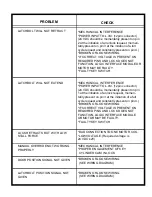
If the lock is not working properly, the following chart may be
used as a guide to locate and correct the problem.
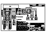
Because the lock receives its signal from the electronic control
system, a thorough check of the control system should be con-
ducted. Using a volt/ohm meter known to be accurate, verify the
correct power signal input at the appropriate connector pin. If the
proper electronic signal is not evident, begin checking “ up-
stream “ from the connector. If the electronic signal input is
correct, the problem is within the locking device, use the follow-
ing chart to locate and correct the problem.
The recommended voltage at the lock is 24 VDC
±
2V. If the correct
voltage is not evident, begin checking “upstream” from the lock.
If the voltage is correct, the problem is within the locking device
or it's logic interface module, use the following chart to locate
and correct the problem.


