background image

For technical problems, please contact the Air-Vac technical service department at:

Air-Vac Engineering Company, Inc.

30 Progress Avenue • Seymour, CT 06483

Phone: 203-888-9900 • Fax: 203-888-1145

e-mail: solder.tech@air-vac-eng.com • www.air-vac-eng.com • 03/26/01

Section 7.0

15V Power Supply Replacement

Replacing your 15V power supply

M4 Allen wrench

1/16” Allen wrench

Slotted screw driver

Black magic marker fine point

15V Power supply part no. 9002.10.010

CHECKLIST:

The following items will be needed in this section.

Read instructions thoroughly before beginning.

BEFORE YOU START:

DRS24C Series

POWER  DOWN  DRS24  AND  DISCONNECT
FROM POWER SOURCE.

ELECTRICAL WARNING:

OBSERVE PROPER STATIC PRECAUTIONS.

CAUTION:

!

Summary of Contents for DRS24C Series

Page 1: ... 01 Section 7 0 15V Power Supply Replacement Replacing your 15V power supply M4 Allen wrench 1 16 Allen wrench Slotted screw driver Black magic marker fine point 15V Power supply part no 9002 10 010 CHECKLIST The following items will be needed in this section Read instructions thoroughly before beginning BEFORE YOU START DRS24C Series POWER DOWN DRS24 AND DISCONNECT FROM POWER SOURCE ELECTRICAL WA...

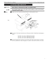
Page 2: ... button head screw B fig 1 and swing right box open Disconnect J1 AC power connector and J2 DC power connector Mark thermocouple plugs as follows wire 126 mark a 1 on both the plug and jack wire 127 mark a 2 on both the plug and jack wire 128 mark a 3 on both the plug and jack Disconnect all plugs and connectors and lay these wires neatly on top of panel This will help avoid any interference of ca...

Page 3: ...caution and do not slide forward fast Be gentile to avoid damage to the DRS and yourself Open right box and move behind the DRS24 The remaining steps will be performed assuming you are located behind the DRS24 Gently slide the power module assembly C fig 2 out of the DRS24 As the power module starts to come out allow the power and thermocouple connectors to fall in front of the module DO NOT FORCE...

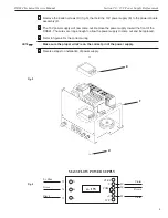
Page 4: ...out Remove the power supply toward the front of the DRS24 The wires are long enough to allow the power supply to come out and be replaced Refer to figure 4 for the correct wiring Make sure the proper wire is on the correct pin of the power supply Reverse steps for installation of power supply NOTE 11 E F D Fig 4 15V N G L 72 74 73 Lt Blue Green Black CTRL W C V COM V 90 Brown 89 Violet 88 Violet M...

Reviews: