DRS24 Technical Service Manual
Section 7.0 : 15V Power Supply Replacement
3
4
5
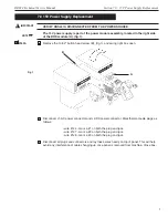
Fig. 2
From bottom of DRS24, remove the four M4 screws that hold the power module assembly in.
USE EXTREME CAUTION WHEN REMOVING SCREWS.
Once the screws from step 4 are removed, slide the DRS24 off the bench in the direction of
the X & Y thumb wheels. Slide the DRS only until the 2 forward feet slide off of the bench.
You will see and hear when the feet have come far enough forward. Use caution and do
not slide forward fast. Be gentile to avoid damage to the DRS and yourself.
Open right box and move behind the DRS24.
The remaining steps will be performed assuming you are located behind the DRS24.
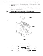
Gently slide the power module assembly (C), (fig.2), out of the DRS24. As the power module
starts to come out, allow the power and thermocouple connectors to fall in front of the module.
DO NOT FORCE THE MODULE OUT. IF IT APPEARS TO BE STUCK, CHECK TO SEE
WHAT WIRES ARE BEING CAUGHT. REMEMBER, THERE ARE WIRES ON BOTH SIDES
OF THE POWER MODULE AND SOME TIMES THEY HAVE TO BE MOVED A LITTLE BIT
TO ALLOW THE REMOVAL OF THE PANEL.
NOTE
☛
NOTE
☛
6
CAUTION
!
7
IMPORTANT
!
C


