


15
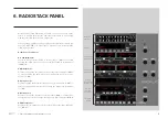
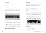
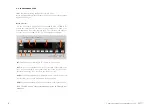
6. RADIOSTACK PANEL - USER’S MANUAL SOLO GA
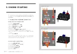
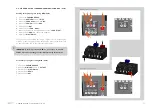
Display
1.
Roll Active Mode
: These can be ROL, HDG, NAV, APR and REV.
• ROL = Wing Leveler active.
• HDG= Heading mode active.
• NAV = NAV1 Radial/GPS track intercepted and following it.
• APR = ILS Localizer captured.
• REV = ILS localizer Back Course captured.
2.
Roll Armed Mode
: These can be NAV, APR, REV and GS. Armed
modes show the ARM caption at its right position.
14.
Altitude selected
: This is the desired or maintained altitude. It can be
changed using the rotary knobs (11).
-
Vertical Speed selected
: This is the selected Vertical Speed.
15.
Alert annunciator
: This label appears when the aircraft altitude is
between 1000 ft and 200 ft of the desired altitude. It always occurs,
even when AP is off or altitude hold is not active.
16.
Pitch Active Mode
: this can be VS, ALT and GS.
• VS: Vertical Speed Mode.
• ALT: Altitude is reached and hold.
• GS: ILS Glide Slope is captured.
-
Pitch Armed Mode
: This can be ALT. Armed modes show an ARM
caption to the right.
17.
Annunciator
: This has two columns, left for AP options and right for
A/T options.
- Left column show the next options:
AP
: Master AP switch is engaged.
YD
: Yaw Damper is On.
FD
: Flight Director is On.
- Right column show:
AT
: Autothrottle is On.
TOGA
: TOGA is On.
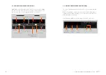
5.
HDG
: Heading mode. This follows the Directional Gyro's or HSI's
"heading bug".
6.
NAV
: Navigation Mode (VOR1 or GPS). Arms the NAV mode to inter-
cept and follow the selected radial on NAV1/GPS track.
7.
APR
: Approach Mode (LOC or ILS). This arms the APR mode, to inter-
cept the Localizer and the Glide Slope (if available and the NAV radio
is tuned to the ILS frequency).
Note: if HDG mode is active, it will be replaced by APR mode when
the Localizer is captured and if ALT mode is active, it will be repla-
ced by the Glideslope when captured.
8.
REV
: Back course mode (Rev LOC). It arms the reverse localizer cap-
ture to perform an outbound procedure turn to ILS.
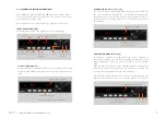
9.
ALT
: Altitude Hold. The altitude maintained is the altitude at the mo-
ment the ALT button is pressed rounded to the nearest hundred. If
the ALT button is pressed with an established climb os decent rate
present, there will be an overshoot, with the airplane returned po-
sitively to the selected altitude. If pressed when ALT hold mode is
engaged, will disengage the mode.
10.
UP & DN
: It is used to change the Vertical Speed (VS) in hundreds.
11.
ALT Knob
: Used to change the selected altitude. The outer knob
changes the altitude in increments of 1000 ft and the inner knob in
increments of 100 ft.
12.
VS
: Vertical Speed. When pressed will engage the vertical speed hold
mode. The vertical speed maintained is the vertical speed present at
the moment the VS button is pressed rounded to the nearest hun-
dred. The rate can be changed using UP or DN buttons. When the VS
button is pressed again, it will disengage the vertical speed mode.
13.
ARM
: This arms the altitude mode. If AP is engaged the plane will
climb or descend to the desired altitude at the selected vertical spe-
ed. Vertical speed can by changed while Alt is engaged by pressing
UP or DN buttons. While altitude is not yet reached, the active mode is
automatically set to VS while ALT is only armed. It will change to active
when the desired altitude is reached.
18.
Yaw Damper
: Switch it ON or OFF (If installed in aircraft being used).