VF-G1000 | User’s manual
5
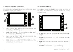
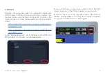
2.2 CONNECTING TO PC
1.
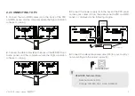
Connect the two HDMI cables (G) to the back of the PFD
and MFD panels and the computer where the flight simulation
software is running.
PC
PFD - MFD
12vdc IN
VGA
HDMI
USB
12vdc OUT
12vdc IN
12vdc OUT
USB
HDMI
Cable (G)
HDMI
Cable (G)
PFD - MFD
12vdc IN
VGA
HDMI
USB
12vdc OUT
PFD - MFD
12vdc IN
VGA
HDMI
USB
12vdc OUT
PFD - MFD
12vdc IN
VGA
HDMI
USB
12vdc OUT
12vdc IN
12vdc OUT
USB
USB
Cable (H)
USB
Cable (H)
USB
Cable (H)
PC
2.
Connect the USB cables (B) to the back of the PFD, MFD and
Audio panels and the computer where the flight simulation
software is running.
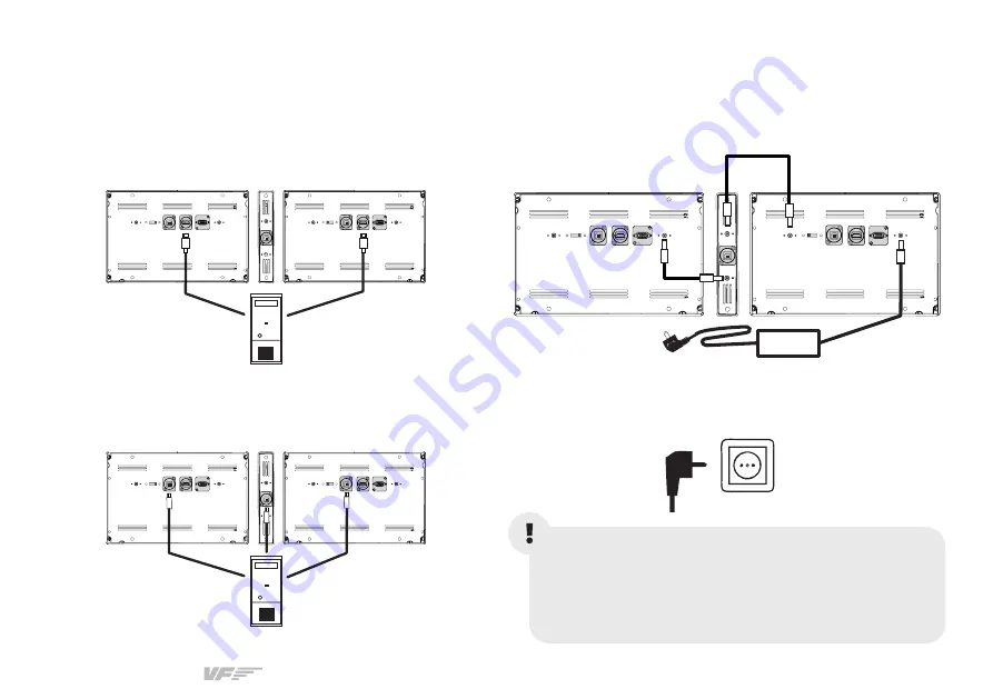
3.
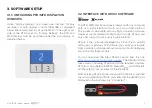
Connect the power supply (C) to the back of the PFD panel
and two jack cables (F) from the Audio panel to PFD and MFD
panels, as displayed in the following diagram.
4.
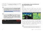
Connect the adequate power cable (D/E) for your country’s
nominal voltage to the power supply (C).
PFD - MFD
12vdc IN
VGA
HDMI
USB
12vdc OUT
PFD - MFD
12vdc IN
VGA
HDMI
USB
12vdc OUT
12vdc IN
12vdc OUT
USB
Jack
Cable (F)
Jack
Cable (F)
Power supply (C)
VF-G1000 Technical Data:
• Nominal current: 0.1A
• Voltage: 100-240 VAC, mono, 50/60Hz
100-240 VAC

