background image

21

CAUTION: Disconnect the linecord from the power entry module 

prior to proceeding.

BULBS

Fluorescent Light Bulb Replacement -AC730:

1. Remove the linecord from the power entry module as shown in figure 5.
2. Using a flat head screwdriver, remove the two bolts holding the light cover in 

place.

3. Firmly grasp the bulb with both hands and rotate the bulb 1/4 turn counter-

clockwise to release. Gently pull down on the bulb, remove it from the fixture, 

and discard.

4. Install the new bulb by sliding into the light socket and turning clockwise 1/4 

turn until it locks into place.

5. Replace the light cover on the front of the enclosure and secure with the two 

mounting bolts.

6. Reconnect the linecord and turn the power back on. See figure 5.

Summary of Contents for PowderSafe AC730C

Page 1: ...OPERATOR S MANUAL Type B Ductless Balance Enclosure Models AC730C AC740C ...

Page 2: ...cifications 6 Product Overview 7 Airflow Diagram 8 Unpacking and Installation 9 11 Controller Instructions 12 14 Operating Instructions 15 Prefilter 16 Main Filter s 18 Filter Serial Instructions 20 Fluorescent Bulbs 21 Cleaning 26 Spare Parts 27 Cart Assembly 28 29 Warranty 30 Shipping Claims 31 Contact Info 32 ...

Page 3: ...2 Electromagnetic Compatibility ESD IEC 61000 4 3 Electromagnetic Compatibility Radiated Immunity IEC 61000 4 4 Electromagnetic Compatibility Fast Transient IEC 61000 4 5 Electromagnetic Compatibility Surge IEC 61000 4 6 Electromagnetic Compatibility Conducted Immunity IEC 61000 4 8 Electromagnetic Compatibility MM IEC 61000 4 11 Electromagnetic Compatibility Voltage Interruption The CE marking ha...

Page 4: ...quipment has been designed tested and certified as complying with the applicable Underwriter s Laboratory USA regulations and recommendations The presence of this symbol means that this equipment has been designed tested and certified as complying with all of the essential requirements applicable to European Union CE regulations and recommendations This symbol alerts the user to the correct replac...

Page 5: ...rly grounded line cord and receptacle Always replace fuses with those specified These instructions must be placed in an easily seen location DO NOT operate the equipment without the filters in place DO NOT use this system until it has been properly installed DO NOT operate this enclosure if the linecord appears damaged or frayed in any way DO NOT attempt to access non user serviceable components o...

Page 6: ... w x 1 h Requirements 1 1 Filter2 HEPA Type ACFHEPA ACFHEPA 42 Weight 9 lbs 18 lbs Dimensions 24 l x 12 w x 3 h 42 l x 12 w x 3 h Requirements 2 2 Options Cart with two 4 locking wheels 32 l x 30 w x 34 h 48 l x 30 w x 34 h NOTE 1 Your enclosure is shipped with the prefilter s attached to the inside of the enclosure AirClean Systems prefilters are filtrete electrostatic particulate filters with 65...

Page 7: ...asy change of all contaminated filters while under negative pressure A permanent HEPA filter protects the operator during primary HEPA filter change out If the primary HEPA filter should ever be compromised it would also act as a permanent nondisturbed backup safety filter The pre filter and primary HEPA filter are simply bagged out within the enclosure OVERVIEW Independently tested and validated ...

Page 8: ...ure while being mixed with contaminated air B 2 At C the contaminated air first enters a roughing pre filter before entering the primary HEPA filter 3 Air cleaned by the primary HEPA filter enters the permanent safety HEPA filter at D 4 Clean air is returned to the room at E AIRFLOW DIAGRAM Figure 1 Airflow diagram ...

Page 9: ...on should not be installed near doors windows or air conditioning heating ventilation systems Air must be allowed to circulate freely around the enclosure Allow at least 6 between the top and the right side of the enclosure and any obstructions 5 If ordered assemble the mobile cart Assembly instructions are included with the cart and also in the OPTIONS section of this manual page 29 6 Designate t...

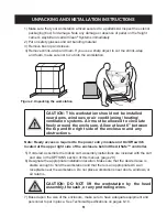
Page 10: ...ecking for any damage that may have occurred in shipping Pay special attention to the sash hinges If damage has occurred call AirClean Systems immediately DO NOT attempt to use workstation 10 Make sure that the rear hatch cover is secure and seated properly See figure 4 Figure 4 730C Rear Figure 3 Lifting the workstation properly Sash Hinges ...

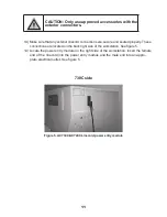
Page 11: ...station See figure 5 14 Locate the power entry module on the right side of the workstation Insert the female end of the linecord into the power entry module and the male end into an appro prate electrical outlet See figure 5 CAUTION Only use approved accessories with the exterior connectors Figure 5 AC730C AC740C Linecord power entry module 730C side ...

Page 12: ...ontinuously display face velocity while blower is activated PUMP Inactive key for enclosure LIGHT One touch to enable fluorescent light TIMER User definable lab event timer AUX Inactive key for enclosure Figure 6 AirSafe automatic safety controller layout CONTROLLER INSTRUCTIONS All other settings are factory pre set and should not be changed ...

Page 13: ...ble alarm active POWER Turns on off power to the controller and its keys This DOES NOT cut off power to the entire enclosure The main power switch is located above the power inlet on the top of each polypropylene fume hood MAIN MENU Displays the time and date when the main power is on and the controller power is off When controller power is activated the screen will display one of the following an...

Page 14: ... audible alarm when it sounds by touching the alarm button on the controller The visible alarm will still work FILTER This menu shows the serial number and the purchase date of the filter For every new filter installed a new filter serial number must be entered Refer to the MAINTENANCE section for complete instructions The first filter serial number has already been entered for you prior to shipme...

Page 15: ...other substances please call AirClean Systems to verify compatibility before use in this case your filter may have another model number Dial 919 255 3220 or 800 849 0472 Monday Friday 8 00 AM 5 00 PM EST 3 Perform any part of your process that involves powders and particulate inside your enclosure NEVER manipulate powders or particulate at the front edge of your enclosure B When working within the...

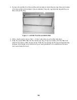
Page 16: ...ur unit The pre filter and pre filter grid are located at the back of the unit 2 Look through the slats on the pre filter grid If the prefilter is discolored the original color is green replacement is needed B To replace the Pre filter 1 Don the proper PPE for handling the substance that have been used inside the enclosure refer to the MSDS sheets 2 Turn the unit on and make sure that the blower i...

Page 17: ...e bag Dispose of the pre filter in accordance with your local guidelines for the substances that have been used inside the hood 6 Inspect the HEPA filter for blockage If replacement is needed refer to the FILTER REPLACEMENT Type B sub section of this manual for complete instructions 7 Place the new pre filter into the pre filter grid and secure into place with the 4 black knobs or 6 polypropylene ...

Page 18: ...is changed prior to the annual date it should be changed every two years from this new date A To remove the spent ACFHEPA filter 1 Turn the unit on and make sure that the blower is running The safety filter located in the top of the workstation will protect you from any residual powders that might come off of the saturated primary HEPA filter while replacing it 2 Place 2 appropriate poly bags on t...

Page 19: ... 5 With a small wrench remove the 20 hex nuts and remove the filter hold down 6 Place the spent HEPA filter into the second poly bag Wipe any residue off of the filter hold down frame and any other obvious areas Place the second rag into the bag and seal the bag Dispose of both bags in accordance with your local guidelines for the substances that have been used inside the hood Figure 11 AC740C Pre...

Page 20: ... properly 1 If the Low Airflow Alarm is not activated proceed to use the enclosure 2 If the Low Airflow Alarm is activated contact our Technical Support Department at 800 849 0472 Direct dial 919 255 3220 Monday Friday 8 00AM 5 00PM EST MAINTENANCE FILTER SERIAL NUMBER ENTRY Press the MODE up arrow key until the filter screen is displayed This screen will display the days remaining for filter life...

Page 21: ...the light cover in place 3 Firmly grasp the bulb with both hands and rotate the bulb 1 4 turn counter clockwise to release Gently pull down on the bulb remove it from the fixture and discard 4 Install the new bulb by sliding into the light socket and turning clockwise 1 4 turn until it locks into place 5 Replace the light cover on the front of the enclosure and secure with the two mounting bolts 6...

Page 22: ... light tray in place located on the right side of the enclosure See figure 11 3 Once the screws are removed slide the light tray until you see the black connector See figure 12 4 Grasp both sides of the electrical connector and turn the collar counter clockwise to release See figure 13 CAUTION Disconnect the linecord from the power entry module prior to proceeding Figure 11 Figure 12 Figure 13 ...

Page 23: ...all the new bulb by sliding into the light socket and turning clockwise 1 4 turn until it locks into place 8 Slide the light tray into place so that you can re attach the electrical connector Turn the collar clockwise to tighten See figure 13 9 Push light tray the rest of the way in and secure into place with the two mounting screws See figure 11 10 Reconnect the linecord and turn the power back o...

Page 24: ...ller so that the left rear corner is in the mounting opening and reattach the two connectors 5 Slide the module into position and replace the two mounting screws 6 Reattach the linecord as shown in figure 5 CONTROLLER WARNING Only remove the controller module under the direction of an AirClean Systems trained technician WARNING If the linecord has not been removed theremaybepotentiallyhazardousvol...

Page 25: ...ning 5 Reattach the two connectors at the rear of the control box 6 Slide the module into position and replace the three mounting screws 7 Reattach the linecord as shown in figure 5 WARNING If the linecord has not been removed theremaybepotentiallyhazardousvoltagespresent behind the controller module ...

Page 26: ...aning chemicals 2 The sash should always be cleaned with an acrylic foam cleaner or a soft damp cloth Do not use solvent cleaners on the sash as this may cloud the sash material WARNING Interior cleaning with an approved disinfectant should be completed routinely WARNING Residual moisture must be removed from the sash or chemical burn may occur If this occurs contact AirClean Systems technical sup...

Page 27: ...12 52178 Hatch Cover Electronics 1 09 50009 Hex Nuts 8 10 03 50184 IEC Connector 1 1 06 50422 Knurled Knob 4 10 51324 Light Fixture 1 10 50778 Light Fixture 1 12 52177 Light Hatch Cover w Welded Support 1 12 52182 Light Tray Assembly 1 01 52053 Power Cord 1 1 12 52179 Prefilter Cover 1 12 52187 Prefilter Cover 1 08 50221 Pressure Switch 1 1 12 52186 Sash Assembly 1 12 52185 Sash Assembly 1 06 5031...

Page 28: ...or the front and back legs of the left end piece f To connect the bottom cross pieces insert bolts into bottom holes and screw in bolts NOTE For more foot access in the front screw the cross piece into the second hole from the bottom on the front end piece legs 2 To attach the casters thread the casters into the end piece legs The two locking casters normally are located in front Hand tighten only...

Page 29: ...LED CART CONFIGURATIONS 2 Cart End Piece 4 Cart Cross Piece 2 Locking Caster 2 Standard Caster 4 Washer 8 1 Washer 4 1 x Bolt 8 2 x Bolt Standard Setup For Seated Use Mounting Holes Hole 3 Hole 5 Hole 4 Hole 1 Hole 2 TOP BOTTOM ...

Page 30: ...If the cause is determined to be a manufacturing fault the dealer or AirClean Systems will repair or replace all defective parts to restore the unit to operation Under no circumstances shall AirClean Systems be liable for indirect consequential or special damages of any kind This statement may be altered by a specific published amendment No individual has authorization to alter the provisions of t...

Page 31: ...very NOTE Do not return any materials without authorization from AirClean Systems Products returned without prior authorization will not be accepted AirClean Systems and its dealers are not responsible for shipping damage The recipient must file claims directly with the freight carrier If authorization has been received to return this product by accepting this approval the user assumes all respons...

Page 32: ...49 0472 Fax 919 255 6120 Email info aircleansystems com Visit AirClean Systems on the Internet at Main website http www aircleansystems com Medical website http www aircleansystems org Forensic website http www aircleansystems net MODEL NO SERIAL NO AC730C AC730C___________ AC740C AC740C___________ CONTACT INFORMATION Raleigh NC 27604 Phone 919 255 3220 Toll Free 800 849 0472 Fax 919 255 6120 Emai...

Reviews: