background image

Sandpiper Installation Guide  

 28

th

 May 2013 – Revision 7 

Page 

8

 of 

22


Cut 65mm diameter holes in the cupboard/wall where 
the ducting outlets will be positioned 


Then place the inner duct piece on the inner side of the 
wall  and  screw  the  outer  duct  piece  on  (leaving  only 
the outer duct piece visible) 


Attach  the  ducting  to  the  walls  or  floor  using  the 
ducting brackets and screws provided  


For ducting running up walls Aircommand recommends 
one ducting bracket per metre of ducting 


Ensure  that  all  ducting  is  secure  on  the  unit  and  also 
where the inner duct piece is attached 
 

3.


Electrical supply and interface 

This  unit  MUST  be  installed  in  accordance  with 
local  wiring  regulations.


Ensure  that  power  is 

properly  disconnected  at  the  supply  (mains  and/or 
battery). Failure to do so may result in personal injury or 
death.


Locate an existing wall socket and plug the unit in 
 

If  the  supply  cord  is  damaged,  it  must  be 
replaced  by  Aircommand,  one  of  its  service 
agents or similarly qualified persons in order to 

avoid a hazard. 


With a flat head screw driver or similar pop off the rear 
cover of the interface 


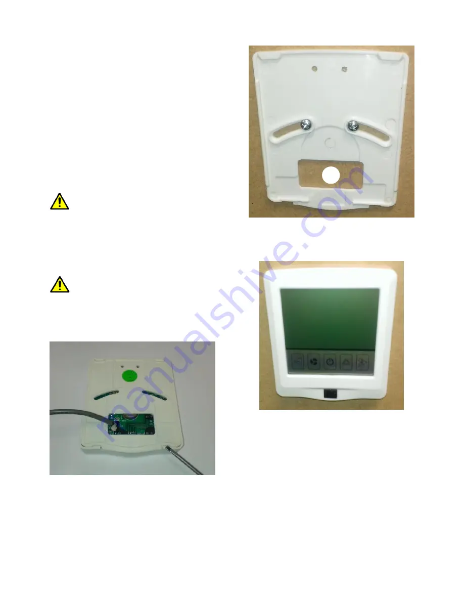
Figure 7-Pop off the rear cover of the interface using a flat head 

screwdriver or similar


Place  the  rear  cover  of  the  interface  in  position  and 
screw to the wall using the screws provided 


Drill a 15mm hole into the wall as shown in Figure 8  


Feed  the  cable  through  the  15mm  hole  and  clip 
interface onto the backing plate (Figure 9) 


Figure 8-Screw the rear cover to the wall and feed cable through 


Locate the interface connection cable at the rear of the 
Sandpiper and connect the two cables 


Figure 9-Replace the front cover of the interface


INSTALLATION IS NOW COMPLETE – 
PROCEED TO COMMISSIONING  


Summary of Contents for sandpiper

Page 1: ...on Guide 28th May 2013 Revision 7 Page 1 of 22 SANDPIPER OWNERS MANUAL INSTALLATION COMMISSIONING OF UNIT MAINTENANCE SPECIFICATIONS OPERATING INSTRUCTIONS CUT OUT TEMPLATES SPARE PARTS WIRING DIAGRAM TROUBLESHOOTING GUIDE ...

Page 2: ...n Adresse registriert werden www aircommand com au registration html GARANTIE DE CLIMATISATION RÉFRIGÉRÉE Garantie pour l Australie Nous nous engageons par cette garantie à faire rectifier gratuitement par notre agent de service tout défaut résultant d un défaut de fabrication ou de remplacer tout composant défectueux dans les 12 mois suivant la date du premier achat de l appareil au détail Cet en...

Page 3: ...CTIONS FOR SANDPIPER AIRCONDITIONER Model Number 7000001 Serial Number Date Purchased WARNING It is important that this installation manual is properly read and understood before installation The unit must be installed by a qualified service technician Failure to properly install the unit or attempting to modify it in any way can be extremely hazardous and may result in property damage and persona...

Page 4: ...ide the van Cook outside if possible Park the caravan RV in a shaded position In periods of extreme high temperature it is recommended to start the air conditioner earlier in the morning to greatly improve its ability to cope with the expected peak heat load III CONDENSATION In areas of high humidity the humid air within the van will cause sweating or condensation in parts of the unit as the humid...

Page 5: ...rews are all the same type of screw BEFORE INSTALLATION Ensure that the installation instructions have been properly read and understood Installation must conform to local wiring regulations DO NOT attempt to modify or add components to the installation procedure This equipment must only be serviced by a licensed refrigeration mechanic If your installation varies from the method outlined please co...

Page 6: ...n appropriate location the cable length from the unit to the touch screen is 4m Extension cables are available contact Aircommand if needed The filter side of the Sandpiper should face the open side of the seat bed where the return air grille is Figure 1 Figure 1 Preferred orientation of the unit where the filter is on the same side and close to the return air grille If this is not possible then t...

Page 7: ...upplied Cupboard seat bed cut out Determine where the return air grille will be placed according to the requirements above If you are using the supplied return air grille then the cut out template can be found at the end of this installation manual Ensure the logo at the top of the return air grille is in the correct orientation Cut out the required hole and secure the grille in place using the su...

Page 8: ...d or battery Failure to do so may result in personal injury or death Locate an existing wall socket and plug the unit in If the supply cord is damaged it must be replaced by Aircommand one of its service agents or similarly qualified persons in order to avoid a hazard With a flat head screw driver or similar pop off the rear cover of the interface Figure 7 Pop off the rear cover of the interface u...

Page 9: ... similar WARNING Airborne particles can pose a health risk particularly to young children and the elderly Ensure that filters are cleaned in a safe and well ventilated area If a more thorough clean is required then the filter can be washed out using warm soapy water Care must be taken to avoid ripping the fabric The filter must be completely dry before reinstallation The filter should be cleaned e...

Page 10: ... Page 10 of 22 If you have a claim please contact Aircommand directly on 08 8345 8444 alternatively you can fax 08 8243 0628 or email service aircommand com au please have your unit serial number ready which can be found on the sticker on top of the unit ...

Page 11: ...A PTY LTD SANDPIPER MODEL NO 7000001 240V 50HZ REFRIGERANT 407C 450G RATED CAPACITY COOLING 2200W RATED CAPACITY HEATING 1800W POWER INPUT COOLING 980 W POWER INPUT HEATING 880 W RATED CURRENT COOLING 4 3A RATED CURRENT HEATING 3 8A MAX INPUT POWER 1150W MAX CURRENT 5A MAX DISCHARGE SUCTION PRESSURE 2800 kPa 700kPa PROOF RATING IPX4 AIR DELIVERY MAXIMUM 120 L s E OE All values are approximate subj...

Page 12: ...nical parts which are protected by grilles but objects of a small enough size may be able to penetrate the inside of the appliance The remote control has the same features as the LCD touchscreen except for the timer function The button icons on the remote may vary slightly compared to the touchscreen LCD TOUCHSCREEN CONTROL PANEL Decrease Fan Speed On Off Mode Increase DAY TIME SETTING Press and f...

Page 13: ...e is close to comfortable but you wish to dehumidify the air Cycle mode button to highlight the snowflake dripping icon Select desired set point temperature by pressing the plus or minus keys or Note the fan speed is locked in LOW The compressor will cycle on and off at approximate intervals of 6 minutes to extract moisture from the air AUTO The Auto mode is used when Turn unit ON Press MODE until...

Page 14: ...e On Off will not be affected by the button lock TEMPERATURE DISPLAY SETTING Press and for 5 seconds to change temperature measurement unit to either or REMOTE CONTROL INSTRUCTIONS The functions on the remote control are the same as on the LCD touchscreen except that the timer function can only be set from the LCD touchscreen see Figure 11 for diagram The functions operate the same way if set by t...

Page 15: ...me during timer clock setting Fan speed Select from High Medium and Low In cooling and heating mode AUTO FAN speed can be selected Mode COOL decrease air temperature DRY dehumidify the air HEAT increase room temperature AUTO automatically selects heat or cooling mode as required FAN circulates air Sleep Allows the controller to gradually depart from the set point temperature while you sleep Timer ...

Page 16: ...Sandpiper Installation Guide 28th May 2013 Revision 7 Page 16 of 22 SANDPIPER FLOOR TEMPLATE ...

Page 17: ...Sandpiper Installation Guide 28th May 2013 Revision 7 Page 17 of 22 ...

Page 18: ...ter 3 6102092 Return air grille 4 5601069 Electronics kit inc touchscreen and remote 5 7001004 Thermostat switch 6 7001006 Top foam canopy Not shown 7001005 Outside fan assembly inc 3uF capacitor Not shown 5601071 Remote control only Not shown 7000001 Sandpiper unit without ducting Not shown 7001009 Buckles and straps all 3 included 7 N A Power cord and separate cable to interface 2 3 1 4 5 6 7 ...

Page 19: ...Sandpiper Installation Guide 28th May 2013 Revision 7 Page 19 of 22 SANDPIPER WIRING DIAGRAM ...

Page 20: ... sensor error E21 outdoor air temperature sensor error Contact Aircommand Australia for specialist advice on fault correction and access to our service agents Poor cooling or heating performance Return air filter is blocked Remove filter clean replace Clean filter every 2 weeks and more frequently with high use Air outlets are closed Ensure that at least 2 outlets are open highest capacity is avai...

Page 21: ...ed RV is too large for the air conditioner The Sandpiper is intended to provide spot cooling and relief to certain areas immediately adjacent to the outlets it is not intended to lower the temperature in all areas of the RV It may do this in some cases but that will depend on the heat load of the van which is affected by size amount of windows insulation persons in the van direct sunlight etc Air ...

Page 22: ...he caravan Unit has been installed incorrectly Refer to instruction manual for correct installation position Timer function does not work Timer function is attempting to be set from using the remote The timer function can only be set from the control pad it will not work if set by the remote refer to operating instructions for more information To display coil temperature a Press and for 3 seconds ...

Reviews: