background image

9

FINISHING THE INSTALLATION 

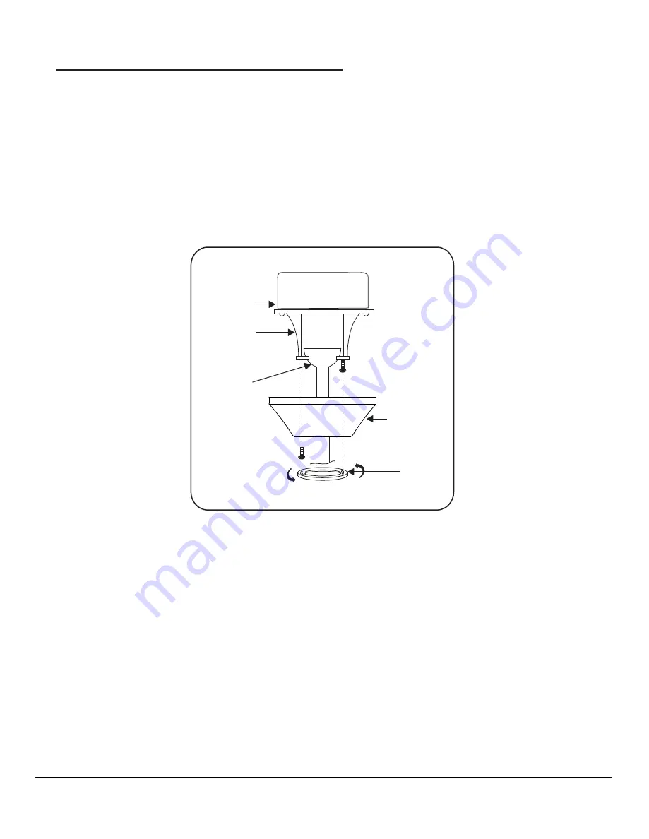
Step 1. Remove 1 of the 2 screws from the bottom of the hanger bracket and loosen the other one half a turn from the 

screw head.

Step 2. Slide the canopy up towards the hanger bracket and place the key hole on the canopy over the screw on the 

hanger bracket, turn canopy until it locks in place at the narrow section of the key holes. (Fig. 14)

Step 3. Align the circular hole on canopy with the remaining hole on the hanger bracket, secure by tightening the two 

set screws.

Note: Adjust the canopy screws as necessary until the canopy and canopy cover are snug.

FIG. 14

OUTLET BOX

HANGER

BRACKET

HANGER

BALL

CANOPY

CANOPY

COVER

Summary of Contents for Spring Haven 04612

Page 1: ...INSTRUCTION MANUAL WARRANTY CERTIFICATE Spring Haven READ AND SAVE ALL INSTRUCTIONS...

Page 2: ...cluding Patent Trademark and or Copyright laws Manual design and all elements of manual design are protected by U S Federal and or State Law including Patent Trademark and or Copyright laws 1151 W Bra...

Page 3: ...is void with the use of any non Aire electrical devices e g wall controls or electrical dimmer switches etc The warranty is void once the original purchaser or user ceases to own the fan or the fan is...

Page 4: ...cked and retightened where necessary before installation 10 Turn the fan off and wait for the blades to stop completely before performing any maintenance or cleaning ATTENTION The Energy Policy Act of...

Page 5: ...with lock washers 21 PCs C Downrod Rubber Cover D Balancing kit 1 Fan blades 5 2 Blade support plates 5 3 Hanger bracket 4 Canopy 5 Canopy cover 6a Standard downrod assembly 6b Minimum length downrod...

Page 6: ...use a plastic outlet box Figure 1 2 and 3 are examples of different ways to mount the outlet box Note You may need a longer downrod to maintain proper blade clearance when installing on a steep sloped...

Page 7: ...up through the downrod Fig 8 Thread Downrod into the Coupling until the holes are lined up and secure with the Lock Pin and Hitch Pin previously removed tighten Set Screws Fig 9 Step 5 Slip coupling c...

Page 8: ...m distance of 40 feet from the transmitting unit for proper signal transmission between the transmitting unit and the fan s receiving unit Step 3 Receiver to House Supply Wires Electrical Connections...

Page 9: ...e key hole on the canopy over the screw on the hanger bracket turn canopy until it locks in place at the narrow section of the key holes Fig 14 Step 3 Align the circular hole on canopy with the remain...

Page 10: ...g and loosen the other 2 screws Do not remove Step 2 Place the key holes from the mounting plate over the 2 screws previously loosened from the mounting ring turn mounting plate until it locks in plac...

Page 11: ...light kit and fan follow the same procedure with the black wire connector from the fan and the black wire connector from the light kit Fig 17 3 Place the key holes from the light kit over the 2 screw...

Page 12: ...before changing the bulb Use light bulb in accordance with the fan s specification DO NOT EXCEED THE MAXIMUM WATTAGE RATING ATTENTION The Energy Policy Act of 2005 requires this fan to be equipped wi...

Page 13: ...r warm or cold weather depend on factors such as room size ceiling height and number of fans The reverse switch is located on the top of the motor housing Slide the switch to the left for warm weather...

Page 14: ...and soapy water 3 If your fan is provided with wood veneer blades you can apply a light coat of furniture polish for additional protection and enhanced beauty Cover small scratches with a light appli...

Page 15: ...screws are tight NOTE All blade sets are grouped by weight Because wood and plastic blades vary in density the fan may wobble even though blades are matched Make sure outlet box is secured to buildin...

Page 16: ...s 52 120 120 120 Fan Size Speed Volts Low Medium High N W G W 1151 W Bradford Court Corona CA 92882 For Customer Assistance Call 1 800 307 3267 For any additional information about your Aire Ceiling...

Reviews: