background image

507148-01

Page 13 of 14

Issue 1406

Heat exchanger cleanout kit #ABRSH380-3 is available for 

purchase.

Emergency Replacement Motor Operation

If the variable speed motor in this furnace needs to be 

replaced in an emergency situation (such as “no heat”) and 

an exact replacement motor is not immediately available, 

a standard PSC motor of equivalent frame size, voltage, 

rotation, and horsepower can be 

temporarily

 installed until 

the correct replacement motor can be obtained.

Connect the desired speed taps to the HEAT and COOL 

terminals and the neutral tap to the neutral terminal on the 

control board (refer to the furnace wiring diagram).

Verify that the unit is operating at the desired speed and 

within the rise range as shown on the unit rating plate.  

The 

correct replacement motor must be installed as soon 

as possible to ensure continued satisfactory operation 

of the furnace.

Emergency Fuel Pump Replacement

If replacement of the A2EA6520 fuel pump becomes 

necessary, replace it with another Beckett CleanCut 

fuel pump.  In an emergency situation where the correct 

replacement parts are not available, an A2VA7116 fuel 

pump could be used.  This option can produce a smoky 

start-up and shutdown that could result in fouling of a heat 

exchanger. 

This is only a short-term option and should 

be used only until the correct parts can be obtained 

and installed.

Complete National Fuel Gas Codes are available from:

1.  American Gas Association


1515 Wilson Boulevard


Arlington, VA  22209

2.  National Fire Protection Association, Inc.


1 Battery March Park


Quincy, MA  02269

3.  American National Standards Institute, Inc.


Publications Sales Department


11 West 42nd Street


New York, NY  10036

MAINTENANCE AND SERVICE

Oil Burner

It is recommended that the nozzle and oil filter be checked 

before each heating season.  Also recheck the conditions 

shown on the 

OIL FURNACE START-UP CHECKLIST


found on page 2. 

Close the oil line shutoff valve if the burner is shut down 

for an extended period of time.

Flue Pipe

Have the flue pipe inspected annually by a qualified service 

technician.  If any soot or ash has formed inside the flue 

pipe, remove and clean.  If the flue pipe has any holes or is 

rusted out, replace with a new flue pipe of the same size. 

Inspect the flue draft control device and replace if defective.

Blower

Blower motor is pre-lubricated and sealed for extended 

operation. No further lubrication is required. The blower 

assembly may be removed from the cabinet for cleaning 

and servicing of the blower.  Disconnect power to the unit 

before servicing.

Heat Exchanger

To clean the heat exchanger:

1.  Remove the vent pipe from the furnace.

2.  Remove the locking screws and the caps from the two 

cleanout tubes; remove the flue access elbow.

3.  Using a long spiral wire brush, sweep down the outer 

drum of the heat exchanger.  Using a shop vacuum hose 

attachment, vacuum out all loose debris.

4.  Remove the locking screw and cap from the inspection 

tube and with the spiral wire brush reach upward 

toward the rear of the heat exchanger to clean out the 

crossover tube; replace the locking screw and cap on 

the inspection tube.

5.  Do not attempt to clean the combustion chamber, as it 

can be easily damaged.

6.  Replace the three previously removed cleanout caps 

and  flue  access  elbow,  making  sure  to  re-install  the 

locking screws.

7.  Brush out and vacuum the vent outlet area of the outer 

drum and reattach the vent pipe.

8.  Clean up around burner, blower deck, and vestibule area.

Summary of Contents for L85BF Series

Page 1: ...actions that could cause property damage personal injury or death WARNING Never burn garbage or paper in the heating system and never leave rags paper or any flammable items around the unit CAUTION This furnace is not approved for installation in a mobile home Do not install this furnace in a mobile home Installation in a mobile home could result in actions that could cause property damage persona...

Page 2: ... adjust pressure to 145 or 150 psig ____________________________________________ Always verify proper pump pressure to corresponding tables with instructions supplied with unit F After 10 minutes of operation obtain flue temperature reading 1st __________ 2nd __________ 3rd _________ G Obtain smoke reading 1st __________ 2nd __________ 3rd _________ H Measure CO2 1st __________ 2nd _________ 3rd _...

Page 3: ...e nearly the same length This allows each room to receive an equal and proper amount of heat This may vary with each particular installation Position the furnace so the pipe connection to the chimney will be of minimum distance and have a minimum of fittings In utility rooms or similar installations the door or access opening should be large enough to permit replacement of the furnace or another a...

Page 4: ...un full size to a location outside the confined space and completely sealed so that no air from the confined space can be circulated through the heating duct system Outdoor Make Up Air A minimum mixed return air temperature of 60 65 F must be maintained for outdoor make up air to prevent condensation and corrosion Venting Chimney Before installing the furnace a thorough inspection of the chimney s...

Page 5: ...ncrete chimney lined with a lining material acceptable to the authority having jurisdiction 11 When two or more appliances vent into a common flue the area of the common flue should not be less than the area of the largest flue or vent connection plus 50 of the areas of the additional vents or flue connections The chimney must be able to sufficiently vent all appliances operating at the same time ...

Page 6: ...n of this furnace has been approved for horizontal venting with the following mechanical vent systems Refer to the manufacturer s installation instructions for proper installation procedures and service parts information Vent systems are available through the local distributor Barometric draft control must be used in the horizontal venting sidewall system It must be located within 18 of the furnac...

Page 7: ...he appliance All wiring must be appropriate Class I wiring Wiring must be installed in rigid metal conduit intermediate metal or be otherwise suitably protected from physical damage Refer to the wiring diagrams supplied with the venter kit for proper electrical connections 2 Visually inspect the venting system for proper size and horizontal pitch and determine there is no blockage or restriction l...

Page 8: ...lected cooling CFM Passive and Active Dehumidification For situations where humidity control is a problem a dehumidification feature has been built into the variable speed motor At the start of each cooling cycle the variable speed motor will run at 82 of the rated airflow for 7 5 minutes After 7 5 minutes has elapsed the motor will increase to 100 of the rated airflow To achieve additional dehumi...

Page 9: ... CFM 50 Static Heat Set ting A Heat Set ting B Heat Set ting C Heat Set ting D Cool Setting A Cool Set ting B Cool Set ting C Cool Set ting D L885UFC67V14 1 2 D 1200 1500 1400 1300 1200 1400 1200 1000 800 L85UFC87V14 1 2 A 1500 1500 1400 1300 1200 1400 1200 1000 800 L85UFC104V20 3 4 C 1550 1850 1730 1550 1400 2000 1800 1600 1200 L85UFC118V20 3 4 A 1850 1850 1730 1550 1400 2000 1800 1600 1200 L85BF...

Page 10: ...ampling hole should be at least two flue diameters above the breech or elbow at the breech but ahead of the barometric damper 2 Operate burner for approximately 5 to 10 minutes 3 Take a draft reading at the service hole in the flue outlet Adjust barometric draft control in the stack to achieve an overfire draft of 01 to 02 and a breach of 02 to 04 4 Pull and record a smoke reading at the service h...

Page 11: ...ent against the center lines marked on the gauge 2 If nozzle is not centered but found to be too far left or right a new nozzle will need to be ordered Do not attempt to adjust by bending the 90 elbow in oil line Sequence of Operation Heating see Figure 13 on page 12 Thethermostatcallsforheat activatingtheburnermotor After a 15 second pre purge period power is sent to the burner and ignition is es...

Page 12: ...dification mode After 7 5 minutes the blower motor runs at 70 of the selected cooling air flow until 1st stage cooling demand is satisfied A call for 2nd stage cooling from the thermostat closes the R to Y2 circuit on the blower interface board The blower motor ramps up to 100 of the selected cooling air flow When the demand for cooling is met the blower ramps down to Y1 until satisfied then ramps...

Page 13: ...s Department 11 West 42nd Street New York NY 10036 MAINTENANCE AND SERVICE Oil Burner It is recommended that the nozzle and oil filter be checked before each heating season Also recheck the conditions shown on the OIL FURNACE START UP CHECKLIST found on page 2 Close the oil line shutoff valve if the burner is shut down for an extended period of time Flue Pipe Have the flue pipe inspected annually ...

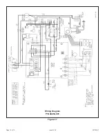
Page 14: ...507148 01 Page 14 of 14 Issue 1406 Figure 17 Wiring Diagram P N 48252 001 ...

Reviews: