Chillers
LOGICOOL™
Chillers
13
Technical Manual : 6521355 V1.14.0 11/2016
Design Features & Information
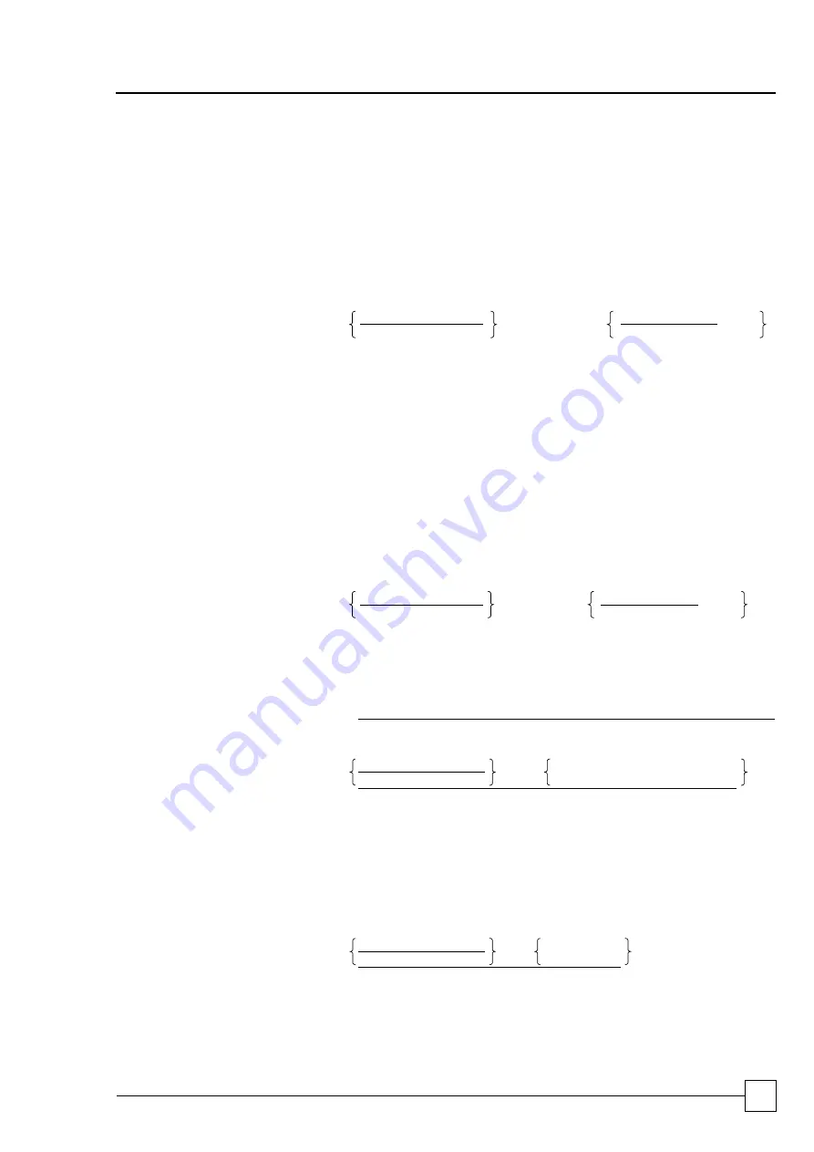
MINIMUM SYSTEM WATER VOLUME CALCULATIONS
(DX Mechanical Cooling Mode Requirements)
General
System fluid 20% ethylene glycol / 80% water.
METHOD 1
Where the system permanent heat load is known and the preferred method:
Vm (l) =
Water Flow Rate
(l/min)
x
Minimum
Compressor Run
Time (min)
x
Chiller Loading
Factor (1)
Vm (l) =
Output x 60
x 2 x
MT x Output
x 1.2
SHC x
ΔT
PHL
(1)
0.1 - 1.00
Where:
Output = (kW)
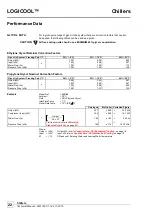
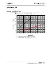
Cooling Duty, Output kW, refer to
SHC
= (kJ/kg°C) Specific Heat Capacity, 3.9 based on 20% ethylene glycol concentration.
ΔT
= (°C)
Difference of Entering Water and Leaving Water temperature
MT
=
Minimum Turndown
PHL
= (kW)
Customer Permanent Heat Load
Example
Model Ref.
=
LCC40
Ambient:
= 35°C
Fluid
= 20% Ethylene Glycol
Inlet Fluid Temp.
= 7°C
Outlet Fluid Temp.
= 12°C (
5°C
T
)
Customer Permanent Head Load
= 20.0 kW
Output at given conditions
= 33.7 kW
Vm =
33.7 x 60
x 2 x
0.10 x 33.7
x 1.2
3.9 x 5
20
Vm =
41.9 L
METHOD 2
Where the system permanent heat load is unknown:
Vm (l) =
Water Flow Rate
(l/hour)
x
Minimum Turndown Ratio
x 1.2
Maximum Number of Compressor Starts (per Hour)
Vm (l) =
Output x 60
x
x 0.1
x 1.2
SHC x
ΔT
10
Example
Model Ref.
=
LCC40
Ambient:
= 35°C
Fluid
= 20% Ethylene Glycol
Inlet Fluid Temp.
= 7°C
Outlet Fluid Temp.
= 12°C (
5°C
T
)
Output at given conditions
= 33.7 kW
Vm =
33.7 x 3600
x
0.1 x 1.2
3.9 x 5
10
Vm =
74.7 L


