


F A N C O
180725
PAGE: 5 / 9
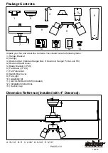
Installation Steps :
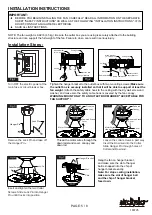
INSTALLATION INSTRUCTIONS
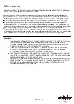
IMPORTANT:
BEFORE YOU BEGIN INSTALLING THE FAN, CAREFULLY READ ALL INFORMATION ON THE SEPARATE
SHEET "SAFETY INSTRUCTIONS" AS WELL AS THE FOLLOWING "INSTALLATION INSTRUCTIONS". IF IN
DOUBT, CONSULT A QUALIFIED ELECTRICIAN.
SAVE ALL INSTRUCTIONS.
NOTE: The fan weight is 9.92 lb (4.5 kg). Be sure the outlet box you are using is securely attached to the building
structure and can support the full weight of the fan. Failure to do so can result in serious injury.
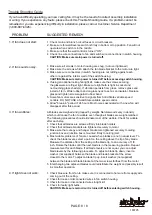
Fig.1
Turn OFF the electric power at the
main fuse or circuit breaker box.
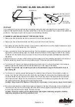
Thread the motor wires through the
downrod stand cover, canopy and
downrod.
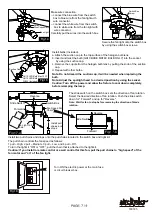
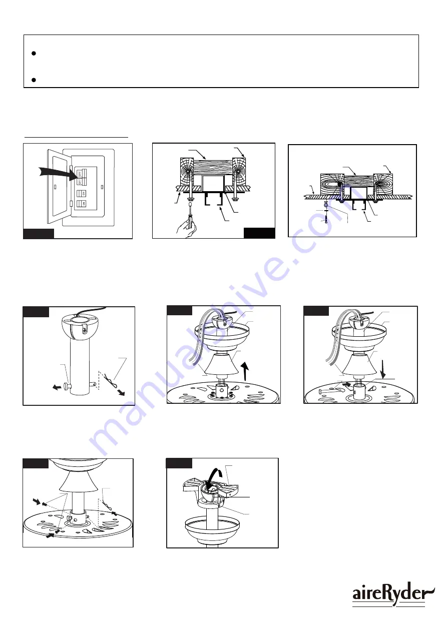
Hanger Pin
Lock Pin
Hang the fan on hanger bracket,
and make sure the slot of hanger
ball is snapped into the chip of
hanger bracket exactly.
Note: For slope ceiling installation,
make sure the slot of hanger ball
and the chip of hanger bracket
face down.
Remove the Lock Pin and take off
the Hanger Pin.
Fig.3
Insert and tighten the two Collar
Screws. Slide Lock Pin into Hanger
Pin until it locks into position.
Fig.6
Lock Pin
Collar Screws
Slot
Chip
Hanger Bracket
Fig.7
Loosen the collar screws in part way.
Insert the Downrod into the Collar.
Slide Hanger Pin through holes of
Collar and Downrod.
Hanger Pin
Motor Wires
Downrod
Downrod Stand
Cover
Collar
Canopy
Fig.5
Motor Wires
Downrod
Downrod Stand
Cover
Canopy
Fig.4
Tighten the hanger bracket to the outlet box with two mounting screws.(
Make sure
the outlet box is securely installed so that it will be able to support at least the
fan weight.
) Attach the safety cable hook to the ceiling with the dry wall screw and
washer, and make sure the safety cable hook is covered by the fan canopy.
WARNING: MOUNT ONLY TO AN OUTLET BOX MARKED "ACCEPTABLE FOR
FAN SUPPORT"!
Fig.5.
Fig.2.
Ceiling
Hanger Bracket
Ceiling Joist
Wood Member
(2" x 4" Approx.)
Junction Box
Washer
Safety Cable Hook
Dry Wall Screw
Ceiling
Hanger Bracket
Ceiling Joist
Wood Member
(2" x 4" Approx.)
Junction Box


